In this article, you’ll learn what is orthographic projection? explained with its examples. Also, download the PDF file of this article at the end.
Orthographic Projection
Orthographic projection is also known as orthogonal projection is a means of representing three-dimensional objects in two dimensions.
Geometrical figures are in two dimensions, hence they may be drawn to their actual sizes and shapes on a sheet of paper as it is also in two dimensions.
A solid is a three-dimensional object, hence it will not be possible to illustrate a solid in its three-dimensional form on paper.
However, solids may be represented on a paper pictorially in its three-dimensional form, but of course not in its true shape and sizes.
- As illustrated drawings do not show the actual shapes of the solids, while reading a pictorial drawing it will be difficult to know the shape of both the interior and exterior of the solid.
- Hence, they can not be used in engineering practice for construction work. Drawings of objects for using in Engg practice, have to be in their true shapes and sizes.
This has been made possible by the “principle of projection” invented by French mathematician Gaspard Monge in 1800, which is the basis for engineering, today’s the most indispensable tool of an engineer to transform ideas into reality.
- The word ‘projection’ is of Latin meaning “to throw forward”.
In the projection method, all the faces of a solid, both visible and invisible, are thrown forward onto a plane. This plane is held normal to the direction of sight of the observer who is viewing the object in the manner similar to that of a motion picture projection, where an image of a film is projected on a screen.
The figure formed by the projection of all the visible and invisible faces of both the interior and exterior of an object is called a “view” in engineering drawings. More than one view of an object is drawn to represent it in true sizes and shapes.
Two Dimensional Projection
Since the visual rays in the figure are diverging, the view of the object will be enlarged. Such an enlarged view of the object will be enlarged. Such an enlarged view although renders the shape of the object but it is rather inconvenient as regards to determining the true sizes of the object because of the extent of enlargement depends on the relative distances between the observer, object and the plane of projection.
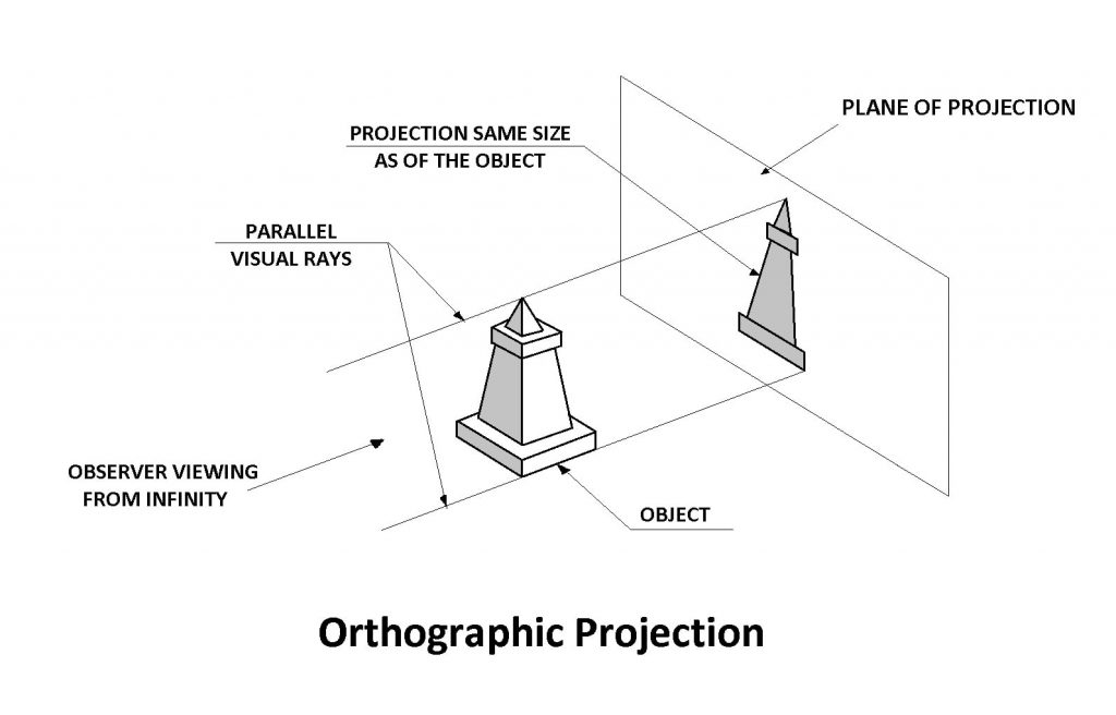
- To obtain the view of the object to the same size as that of the object, the visual rays should run parallel to each other and perpendicular to the plane of projection.
- This will be possible only when the observer is at infinity.
The figure shows the view of an object projected to the same size by the visual rays coming from the observer at infinity which are parallel to themselves & perpendicular to the plane of projection.
Since the visual rays, called projectors, are perpendicular, i.e., orthogonal to the plane of projection the view is called orthographic view and the projection method is called orthographic projection. The orthographic projection method is employed in making engineering drawings.
Projection of an Object
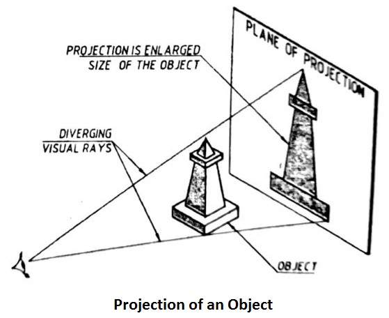
- The figure shows the method of projection of an object.
- An object is placed in front of a plane of projection and an observer is at a finite distance from the object.
- The rays from the observer’s eye called visual rays to pass through all the points on the contour of an object and intersect the plane of projection.
- These points of intersection when joint form the view of the object on the plane of the project.
Principle Views and Principle Planes of Projection
- The orthographic view shown in the figure is obtained by viewing the object from the front, hence called “front view”.
- Since the plane of the project is verticle, it is called a ” verticle plane”.
- The front view alone cannot describe the shape and sizes of the object completely as it only shows two dimensions, viz, height and width.
- It does not reveal the depth dimension as it lies along the direction of the sight for the front view.
- In order to show the depth of the object, one more view is drawn, along with the front view.
- The view from the above, called top view, is drawn which enables the projection of the depth dimension along with width dimension.
- To project the top view, a horizontal plane is placed underneath the object as shown in the figure.
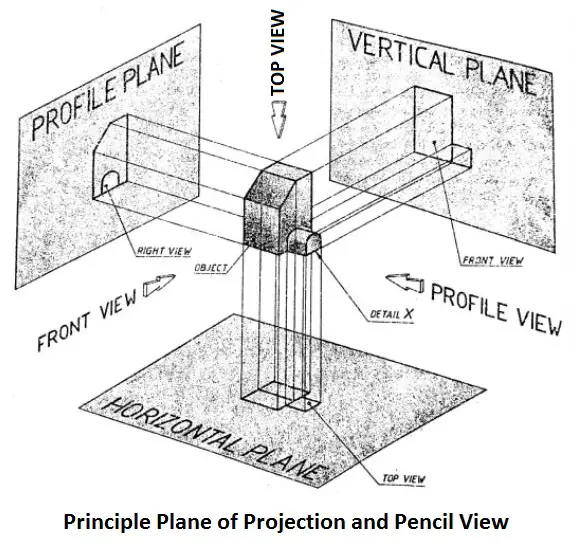
Some times, in order to show some of the details of the object lying either on it’s left or right side which cannot be understood clearly from the top and front vies, side views, called profile view, either left or right, both are drawn along with top and front views. To project the side views either left or right side plane is setup. In the figure, in order to show the detail X of the object, the right view is projected on the left plane.
The vertical, horizontal, and profile planes are called the three principle planes of the projection. The view projected on them namely, front top and profile views are called principle views. The vertical, horizontal, and profile planes are abbreviated a VP, HP, and PP respectively.
Conclusion
That’s it, thanks for reading. If you have any questions about “orthographic projection” ask in the comments below. If you like this article please share with your friends.
Download the PDF file of this article from here:
Subscribe to our newsletter to get notification of new articles.
Read Next: