In this article, you will learn what is pneumatic valves? Its parts, working, and types of pneumatic valves are explained with pictures.
You can also download the PDF file at the bottom of this article.
What is Pneumatic Valve?
The valves that are used to control the pressure, direction, and flow rate of compressed air are called pneumatic valves. Pneumatic systems rely on the force of compressed air to transmit power and can be found in countless applications, such as power tools for diesel engines.
As the air pressure increases, the compressed air begins to push against the walls of the piston or diaphragm, resulting in activating the valve. The valve opens or closes depending on where it is being used.
These valves often serve one of two functions. The first activates a system when a specific pressure is reached. The second prevents damage by maintaining the flow rate inside the system or by releasing pressure when an excessive level is reached.
To further understand pneumatic valves, we will explore the different types of pneumatic valves and how they are used. So let’s get started.
Don’t Miss: Different Types of Pumps and Their Working & Uses
Types of Pneumatic Valves
Based upon the function and internal mechanism, the valves are classified as follows:
- Flow control valves
- Pressure regulator
- Pressure relief valve
- Sequence valve
- Pressure reducing valve
- Direction control valve
- Two-way valve
- Three-way valve
- Four-way valve
Read Also: What is the difference between Hydraulics and Pneumatic?
#1 Flow Control Valves
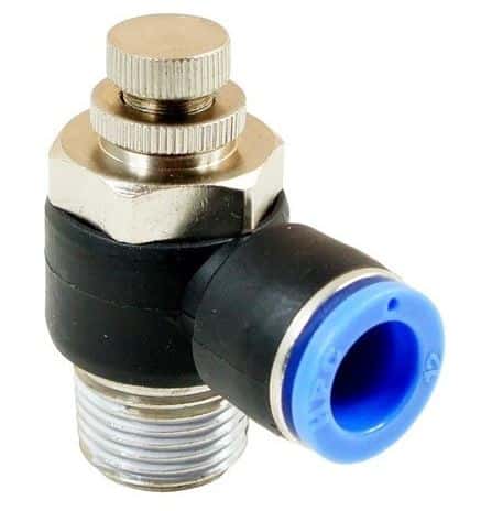
A pneumatic flow control valve adjusts and controls air volume flow within a pneumatic system. In addition, these valves can often use them to adjust the speed of operation of an actuator. While there are many types of flow controllers, they all work on a simple basic principle.
Many flow control valves often have a machined tapered stem that exactly matches the seat’s profile. Fully closed type, there is no airflow; As the valve is progressively opened, more and more air is allowed to flow through. Whereas in the fully open type, the air will pass through the maximum rated flow of the device.
#2 Pressure Regulator
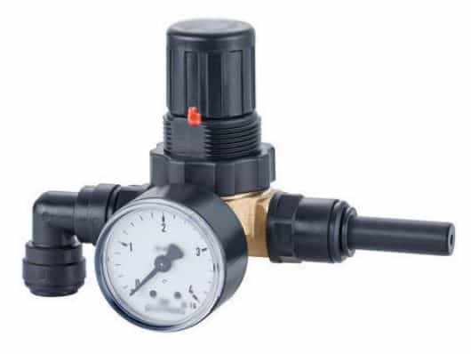
It is a valve that controls the pressure of a liquid or gas to the desired value using negative feedback from the controlled pressure. Pressure regulation matters for all media flowing in pipelines. This type of pneumatic valve consists of a pressure setting, restrictor, sensor, controller, and flow valve.
These valves include a variety of pressure-retaining, reducing, and relieving valves that provide safe and efficient operation and automatically respond to changes to maintain the set pressure. Pressure regulators are used for gases and liquids.
#3 Pressure Relief Valve
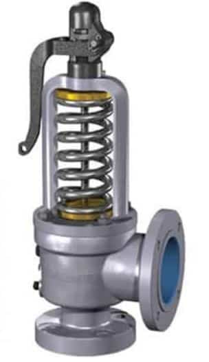
The inlet port is connected to a line of which the maximum pressure is to be controlled and the outlet port is connected to the reservoir. The line pressure at which the poppet will open and fluid will start going to the reservoir depends upon the strength of the spring.
An adjustment screw is provided to adjust the pressure at which the valve will open and the system will start delivering the fluid to the reservoir.
When outlet resistance is increased due to overload, the relief valve functions as follows. The valve piston has a smaller cross-section at the bottom and a large cross-section at the top. At the operating pressure, the differential thrust is equal to the tension in the spring and the exhaust port is completely blocked by the valve piston.
When pressure is more than the operating pressure, the differential thrust of the valve piston exceeds the tension in the spring, and the valve piston is lifted to allow some oil to flow through the exhaust port until the pressure at the outlet is equal to the operating pressure.
Read Also: What is Venturimeter and How does it work?
#4 Sequence Valve
Sequence valves manage the sequence of operations between two separate circuit units, allowing one unit to activate the other unit. It controls the airflow using check valves, flow control valves, air tanks, switching valves, and actuators in sequence.
Pneumatic valves are known for compact and high-performance sealing structures and can be built into fixtures for machining centers. They usually do not require electrical control to operate. These are used in automobile engines, the fuel must move from the tank to the cylinder before the piston can rotate the crankshaft.
#5 Pressure Reducing Valves
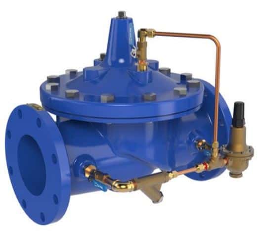
These valves are used to get precise control of the downstream pressure. The valve opens when the pressure drops and closes as it rises. It uses a spring mechanism against a diaphragm or piston as a control element, making them simple and reliable in operation.
They can enable quick action by instant sensing and adjusting based on downstream pressure. An appropriately selected pressure-reducing valve can be used for water hammer protection under defined conditions. In addition, they are also used as a by-pass valve to protect the system during power failure.
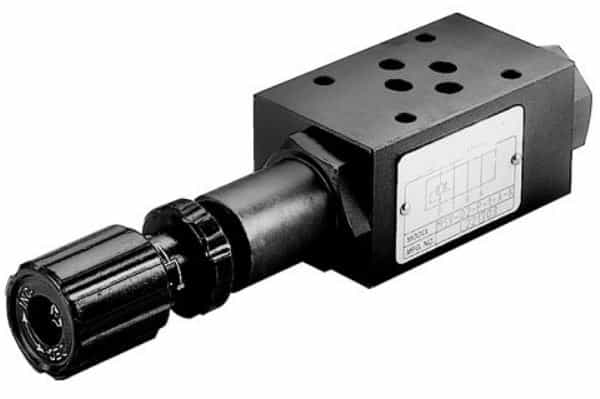
#6 Direction Control Valves
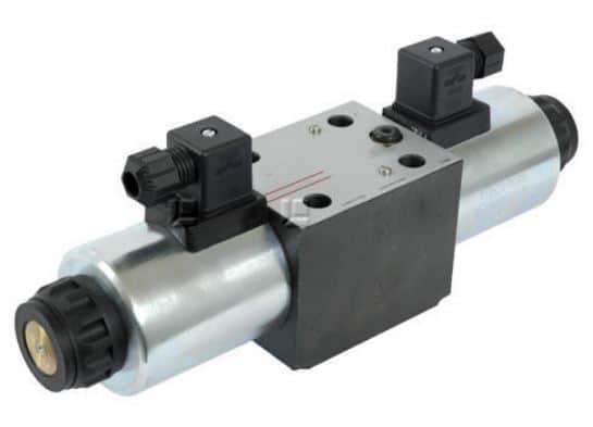
DCVs allow liquids or gases to flow in separate paths from valve ports, providing a way for flow from one or more sources. They are probably used in pneumatic systems and can be used to actuate a cylinder, a large industrial valve, or an air tool.
Direction control valves typically have a spool inside a cylinder that is either mechanically or electrically actuated. The position of the spool limits or allow flow, thus controlling fluid flow. In addition to their pneumatic applications, they are also used in hydraulic systems.
Read Also: What are the Applications of Bernoulli’s Equation?
#7 Two-way Direction Control Valve
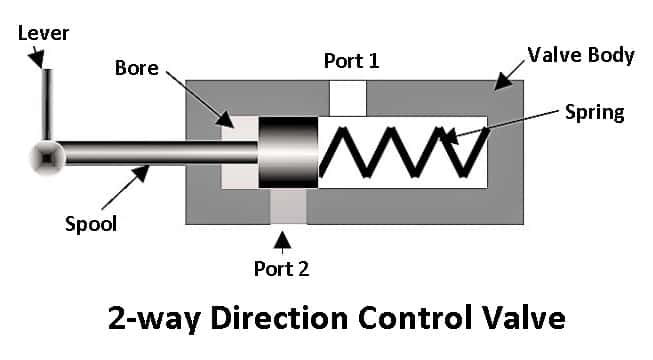
A two-way valve consists of two parts. One port allows the air to come in (inlet port). Another port through which the oil comes out (outlet port). At some points in the operation of these valves, the two passages are connected, at another point, they are disconnected.
When the actuator is in normal position, the inlet port and passage are shut off from the outlet port and passage. In order to connect these two passages, the valve operator must function properly.
In a normally open valve, the inlet passage and outlet passage are connected when the actuating mechanism is in a normal position. These are used to shut off airflow, bleed-off pressures, and actuate pilot-operated control valves.
#8 Three-way Direction Control Valve
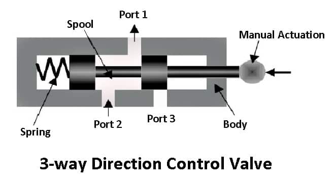
This type of valve has three ports and three internal passages. One port allows the fluid to enter the valve (inlet port). Another port allows the fluid to leave the valve and pass to some means of operation (cylinder port). The third port allows the fluid to exhaust (exhaust port).
In one of the positions of the actuator, the inlet passage is connected to the cylinder passage and the exhaust passage is connected to the cylinder passage, and the exhaust passage is blocked off.
In the other position of the actuator, the inlet passage is blocked and the cylinder passage is connected to the exhaust passage. Three valves that have two inlet ports and one outlet port are in use.
Related: Define Fluid & Types of Fluids in Fluid Mechanics
#9 Four-way Direction Control Valve
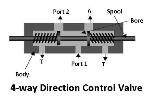
The valve has four ports and four internal passages. One port receives the fluid (inlet port). Another port allows the fluid to exhaust (exhaust port). There are two cylinder ports that direct the fluid to the cylinder. The cylinder ports are usually numbered 1 and 2. Four-way valves are used to actuate a double-acting cylinder.
Four-way valves may be further classified as 2-position and 3-position four-way valves:
1. 2-position Four-way Valve
A 2-position four-way valve means that the actuator has two positions. In one position, the inlet port is connected to cylinder port 1 and the exhaust is connected to cylinder port 2. In the other position of the actuator, the inlet port is connected to cylinder port 2, and the exhaust is connected to cylinder port 2.
2. 3-position Four-way Valve
In 3-position four-way valve, one position is called a center or natural position. In two other positions, the connections are as in 2-position four-way valve.
Read Also: Types of Manometers: Their Working & Applications
Designation and Configuration of Pneumatic Valve
Within the types of pneumatic valves, there are some specific valve configurations that reflect parameters such as port, switching position, and non-activated state (open or closed). When understanding this, a standardized numbering system is used that consists of two numbers separated by a slash (/).
The first number indicates the number of ports in the valve, and the second number indicates the number of switching positions. For instance, a 2/2-way pneumatic valve is a valve with two switching positions and two ports.
Similarly, a 3/2-way valve is three ports with two-position valves. By stretching, a 4/2-way valve has four ports and two switching positions; 5/2-way valves have five ports and two switching positions.
In addition, there is also a non-active state type valve that deals with flow control. A 2/2-way valve may be available in a normally closed position which means the valve is closed and does not allow air to flow between the ports. The best configurations for commonly used pneumatic valves include 5/3, 5/2, 4/2, 3/2, and 2/2.
Specifications for Pneumatic Valves
There are some critical specifications for pneumatic valves which are summarized below. These parameters are for general guidance and you should be aware that different valve manufacturers and suppliers may mark their valves differently.
#1 Operating Pressure
The operating pressure refers to the pressure or range of pressures (for example in psi, Bars, or Pa) which the valve is rated to handle.
#2 Operating Medium
This is the type of media that the valve can control safely. In most cases, this must be compressed air.
#3 Flow Capacity or Coefficient
A measure of a valve’s ability to move or flow air through it, with the flow coefficient (CV) representing the proportionality between the flow rate and the differential pressure.
#4 Cycle Rate
This is the maximum number of valve cycles at which the valve can operate per unit time.
#5 Response Time
Response time refers to the time required for the valve to activate the states or positions once.
#6 Size of the Port
The given physical dimensional parameters determine the port size and thread style on the valve.
#7 Coil Rated Voltage
It is the maximum voltage that the actuation coil can maintain for electrically actuated valves. It is rated in DC and AC volts.
Checkout: What are the types of Mechanical Pressure Gauges?
Wrapping It Up
As we discussed above, the pneumatic systems generally use compressed air to do work. By controlling this air in the system, we can easily convert energy into controlled movement. These pneumatic valves are essential in pneumatic systems and even hydraulic systems.
So for now, I hope that you have learned about the “Pneumatic Valves“. If you have any questions or doubts about this article, feel free to ask in the comments. If you got this article helpful, please share it with your friends.
Want free PDFs in your inbox? Then subscribe to our newsletter.
Download PDF of this article:
You might like to read more in our blog: