In this article, you will learn what is a servo motor? Its diagram, definition, parts, types, function, advantages, and applications are explained with Pictures.
If you need a PDF file? Just download it at the end of the article.
What is a Servo Motor?
Definition of Servo Motor:
A servo motor is defined as a linear or rotary type of actuator that provides fast precision position control for closed-loop position control applications.
As compared to large industrial electric motors, servo motors are not useful for continuous energy conversion. These motors have a high-speed response due to how inertia and are designed with small diameters and long rotor lengths.
Servo motors have a mechanism that uses position feedback to control the speed and final position of the motor. Internally, a servo motor combines a motor, feedback circuit, controller, and another electronic circuit.
These types of motors are best suited for smaller applications. With the advancement of microprocessors and power transistors, AC servo motors are used more often due to their high accuracy control.
Read Also: What are the different types of electric circuits and their working?
Construction of Servo Motor
It uses an encoder or speed sensor to provide speed feedback and position. This feedback signal is compared with the input command position (desired position of the motor corresponding to a load) and produces the error signal (if there exists a difference between them).
The error signal available at the output of the error detector is not enough to drive the motor. So the error detector followed by a servo amplifier raises the voltage and power level of the error signal and then turns the shaft of the motor to the desired position.
Essentially, servo motors are divided into AC and DC servo motors based on the supply used for their operation. Brushed permanent magnet servo motors are used for simple applications due to their low cost, efficiency, and simplicity of working.
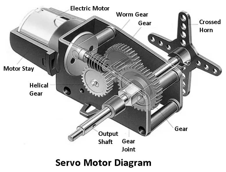
Parts of Servo Motor
Following are the main parts of a servo motor:
- Housing
- Motor shaft
- Bearings
- Rotor
- Stator
- Brake
- Snap ring
- O ring
- Bearing keeper
- Encoder
#1 Housing
It is about 1 inch thick coated aluminum housing that surrounds the inner parts of the servo motor so that it protects the motor from external particles. The motor’s housing is designed for quick and easy disassembly and reassembly.
#2 Motor Shaft
It works similar to a prime mover, whereas the gearbox or belt and pulley system to which it is attached can use that energy to increase the motor’s torque while reducing the motor’s speed. The motor is generally made from cold or hot-rolled steel.
#3 Bearings
Bearings can provide high accuracy and very low vibration to the motor. The result is a very smooth and cool operation. Bearing life will be improved by using new greases and methods to reduce fret.
#4 Rotor
The rotor is usually attached to the shaft of the motor and is placed between two bearings. The rotor is the moving part of the servo motor. With the given voltage, the rotor of the motor rotates in the required direction until the error is zero.
#5 Stator
It is the stationary part of the servo motor. The function of the stator is to create a rotating magnetic field to generate torque efficiently. It is usually made up of 12 individually wrapped winding segments connected by a single copper wire.
#6 Brake
Brakes are used to hold things when the machine is turned off or the E-stop is activated, it is made up of only a few parts. Keep in mind that the spring will let go when voltage is applied, so care should be taken when releasing the brakes as the motor will fall.
#7 Snap Ring
Using a snap ring minimizes damage to the motor while maintaining the shaft position after a direct hit or nudge from an unwanted force. Without it, the shaft could easily slide back into the housing.
#8 O Ring
An O-ring is placed between the two parts to form a seal to stop fluid from entering. O rings are made of plastic polymers and servo motors consist of multiple o-rings.
#9 Bearing Keeper
A bearing keeper is a handheld plate located close to the pulley end that prevents the bearing from slipping out of place.
#10 Encoder
An encoder is an electro-mechanical device used to transmit the speed and direction of a motor back to the drive. This allows the operator to observe and adjust certain parameters on demand. These are light in weight and are quite compact.
Servo Motor Working Principle
The servo motor works on the principle of the pulse width modulation method. In this, the angle of rotation is controlled by the duration of the applied pulse to its control pin. Essentially, the servo motor is a type of DC motor controlled by a variable resistor (potentiometer) and some gears.
Read Also: What is a capacitor and how does it work?
Working of Servo Motor
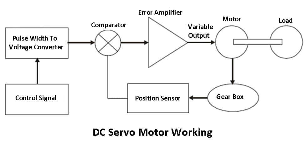
A DC servo motor consists of a DC motor, a position sensing device, a gear assembly, and a control circuit. The DC servo motor has a small DC motor is employed for driving the loads at a precise speed and position.
Now, a DC reference voltage is set to the corresponding desired output. This voltage is applied using a potentiometer by controlling the pulse width to the voltage converter or via a timer depending on the control circuitry. The dial on the potentiometer generates a related voltage which is then applied to the error amplifier.
In some circuits, a pulse control method is used to create a DC reference voltage corresponding to the desired position or speed of the motor. It is then applied to the voltage converter by the pulse width.
Through this converter, the capacitor begins to charge at a constant rate when the pulse is high. Then the charge on the capacitor is fed to the buffer amplifier when the pulse is low and this charge is further applied to the error amplifier.
So the length of the pulse decides the voltage applied at the error amplifier as the desired voltage to produce the desired speed or position.
The feedback signal corresponding to the present position of the load is obtained by using a position sensor. This sensor is normally a potentiometer that produces the voltage corresponding to the absolute angle of the motor shaft through the gear mechanism.
Servo Motor Mechanism
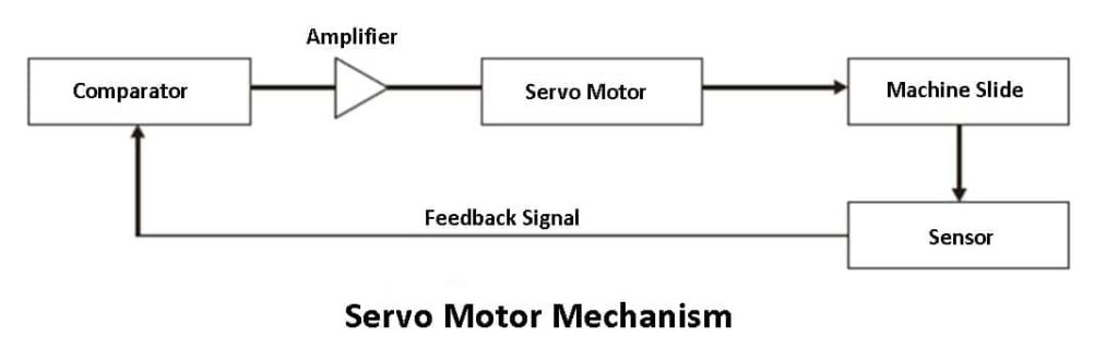
A servo system mainly consists of three basic components – a controlled device, an output sensor, and a feedback system.
This is an automatically closed-loop control system. Here instead of controlling a device by applying a variable input signal, the device is controlled by a feedback signal generated by comparing the output signal and reference input signal.
When a reference input signal or command signal is applied to the system, it is compared with the system’s output reference signal produced by the output sensor and a third signal made by the feedback system.
This third signal acts as the input signal of the controlled device. This input signal to the device presents as long as there is a logical difference between the reference input signal and the output signal of the system.
After the device achieves its desired output, there will be no longer a logical difference between the reference input signal and the reference output signal of the system.
Then, the third signal produced by comparing these above signals will not be sufficient to further operate the device and produce a further output of the system until the next input signal or command signal is applied to the system.
Hence the primary task of a servo mechanism is to maintain the output of a system at the desired value in the presence of disturbances.
Read Also: 10 Different Types of Insulators Used In Transmission Lines
Types of Servo Motor
Following are the types of servo motor:
- DC servo motor
- AC servo motor
- Positive rotation
- Continuous rotation
- Linear servo motor
#1 DC Servo Motor
This type uses separate DC sources in the field of winding & armature winding. A DC servo motor consists of some components which are a small DC motor, feedback potentiometer, gearbox, motor drive circuit, and feedback control loop. It is quite similar to the normal DC motor.
Motor control by controlling armature current or field current. These provide a very precise and fast response to the start or stop command signal due to low armature inductive reactance. These motors are used in computerized numerically controlled machines.
#2 AC Servo Motor
AC motors include encoders that are used with controllers to provide feedback and closed-loop control. This motor can feature high accuracy and has a high design of tolerances. Some designs also use higher voltages to obtain more torque.
They are used in automation, robotics, CNC machinery, and other applications for the high degree of accuracy and versatility required.
#3 Positive Rotation
In this motor, the output shaft of the motor rotates 180 degrees. The motor mainly consists of physical stops which are in the gear mechanism to prevent the rotation sensor from rotating. These are commonly seen in radio-controlled water, radio-controlled cars, planes, robots, toys, etc.
#4 Continuous Rotation
These are standard servo motors that have been modified to provide open-loop speed control instead of their usual closed-loop position control. The control signal is interpreted as the speed and direction of rotation, rather than determining the position of the servo.
Servo to rotate clockwise or counterclockwise in the range of possible command sources at varying speeds. The application is found in a drive motor on a mobile robot.
#5 Linear Servo Motor
Linear servo motors fall into a class of positional rotation servo motors, but with an additional set of gears to convert the O/P back and forth from circular. These servo motors are rarely found but are sometimes they are used as actuators in higher model airplanes.
Read Also: What are the different types of transformers?
Advantages of Servo Motor
- They have the ability to produce high output power relative to motor size and weight.
- It has high efficiency and can reach 90% at light loads.
- The motor provides high torque to inertia ratio and can accelerate loads rapidly.
- It can provide quiet operation, run smoothly, and provide high accuracy.
- The position of servo motors can be controlled more precisely as compared to other DC motors.
Disadvantages of Servo Motor
- The drawback of the servo motor is that it demands tuning to stabilize the feedback loop.
- If something breaks, the motor will be unreliable. Therefore, a protection circuit is required.
- The overall system cost and installation cost are higher than that of a stepper motor due to the need for feedback components.
- It would require a complex controller to provide the encoder and electronic support.
Applications of Servo Motor
Following are the applications of servo motor:
- The servo motor is used in robotics to activate movements, giving the arm its precise angle.
- These are used to start, move, and stop-conveyor belts carrying the product along with many stages. For instance, product labeling, bottling, and packaging.
- The servo motor is built into the camera to correct the lens of the camera to improve out-of-focus images.
- This motor is used in a robotic vehicle to control the robot wheels, Producing plenty of torque to move, start and stop the vehicle and control its speed.
- These are also used in the solar tracking system to correct the angle of the panel so that each solar panel stays to face the sun. In addition, These are also used in metal forming and cutting machines to deliver specific motion control for milling machines.
- Servo motor is used in Textiles to control spinning and weaving machines, knitting machines, and looms.
- The servo motor is used in automatic door openers to control the door in public places like supermarkets, hospitals, and theatres.
- In Automobiles, servomechanism is used in power steering, braking system, and cruise (speed) control.
Conclusion
In short, servo motors are used in many industries and have many advantages as we discussed above. They offer many solutions regarding mechanical concerns and have features that make them powerful and efficient.
So for now, I hope I’ve covered everything you were looking for about “Servo Motor”. If you still have any doubts or questions regarding this topic, leave a comment below I’ll definitely reply. If you liked it, then share this with your friends.
Want free PDFs direct to your inbox? Then subscribe to our newsletter.
Download PDF of this article:
You might like to read more in our blog regarding automobile engineering:
hello interesting topic,may i kindly ask for a copy of the pdf getting sent to [email protected]
kind regards
The PDF file has been sent to your inbox.
Sent me the download link please
The PDF file has been sent to your inbox.