In this post, you’ll learn about the steering system and its working, types of steering systems with parts, functions, and types of steering gears.
Steering System
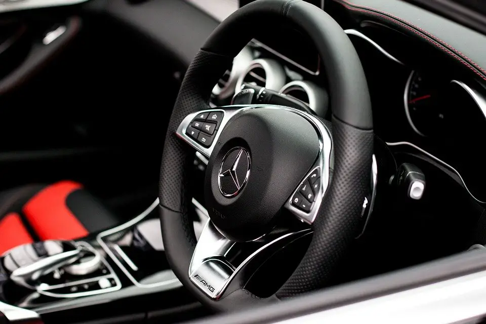
The car steering system or just the steering system is the most important part of automobile vehicle steering control, responds so well to the driver while driving. Steering control makes you feel safe while driving.
The car steering system in the automobile is the process of running the vehicle in the desired direction by turning, usually the front wheels. For effective control of the vehicle throughout its speed range with safety, proper steering is necessary.
The system allows a driver to use only light forces to steer a heavy car.
Steering is also possible by turning the rear wheels, which is used generally in low-speed slow-floor vehicles, for lifting and transporting heavy parts over a short distance for example, a forklift.
If you’d like to know all about the car steering system. Like how it works, What are the types of steering systems, How it supports handling, and road holding and driveability, then please continue reading.
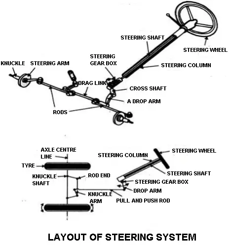
Automobiles are always equipped with front-wheel steering. A simple sketch of a car steering system is shown in the figure.
The Basics of Steering System
Steering a vehicle is pretty easy stuff right, do you know how it works it seems so simple but it’s not. Let’s take a look at what your vehicle’s moving parts are actually doing.
As you turn the steering wheel the steering shaft rotates the pinion gear. The teeth of the pinion gear and the steering rack interlock as the pinion rotates.
This rotation will push the rack when the rack moves the attached rods and steering knuckles act as pivot points and turn the front tires.
For example, rotating the steering wheel to the left will push the rack to the right pivoting the front tyres to the left.
The more you turn the steering wheel the more rack is pushed and the sharper the turn will be a little confusing well don’t worry you don’t have to be a mechanic to steer a vehicle but we wanted you to have a visual of exactly that is occurring when you make that turn of the wheel.
Although there are many moving parts and words you have never heard of with little effort and the help of your steering system it’s easy to steer your vehicle.
How does a Car Steering System work?
The steering system will convert the rotary motion of the steering wheel into the angular turn of the front wheels.
- The steering wheel rotates the steering column.
- The steering gearbox is fitted to the end of this column. Therefore, when the wheel is rotated, the cross shaft in the gearbox oscillates.
- The cross shaft is connected to the drop arm. This arm is linked using a drag link to the steering arms.
- Steering arms on both wheels are connected by the tie rods to the drag link.
- When the steering wheel is operated the knuckles move to and fro, moving the steering knuckles are connected.
- One end of the drag link is connected to the tie rod. The other end is connected to the end of the drop arm.
The Purpose of a Steering System
For effective control of the vehicle throughout its speed range with safety and without much effort to the driver on different types of road surfaces, proper steering is necessary.
For proper performance and useful service of the automobile, it is necessary that the moving vehicle should be under the perfect control of the driver. Thus the control of the automobile is done by means of a steering system that provides directional changes to the moving automobile.
Function of Steering System
The important function of the steering system is as follows:
- With the help of the steering system, the driver can control the vehicle however he wants
- The steering provides stability to the vehicle on the road.
- It minimizes tyre wear and tear.
- It prevents road shocks from reaching to the driver.
- The steering provides self-rightening effect after taking a turn.
Wheel Alignment
Wheel alignment is defined as the correct adjustment of the pivot axes controlling the movement of the wheels.
The wheels alignment, therefore, refers to the correct positioning of the front wheels and steering mechanism for the promotion ease of steering, reducing tyre wear to a minimum as well as providing directional stability to the vehicle.
Proper aligned front wheels result in.
- Steering comfort.
- Uniform wear of tyres.
- Minimum energy consumption.
- Minimum vibrations.
- No wheel wobbling.
- Reduce the driver effort to turn the vehicle.
- To achieve self-centring of the wheel after turning.
- To achieve directional stability of the vehicle while running.
Types of The Steering System in an Automobile
Following are the three types of steering systems:
- Bicycle steering.
- Turntable steering or centre pivot steering.
- Ackarman steering or side pivot steering.
#1 Bicycle Steering
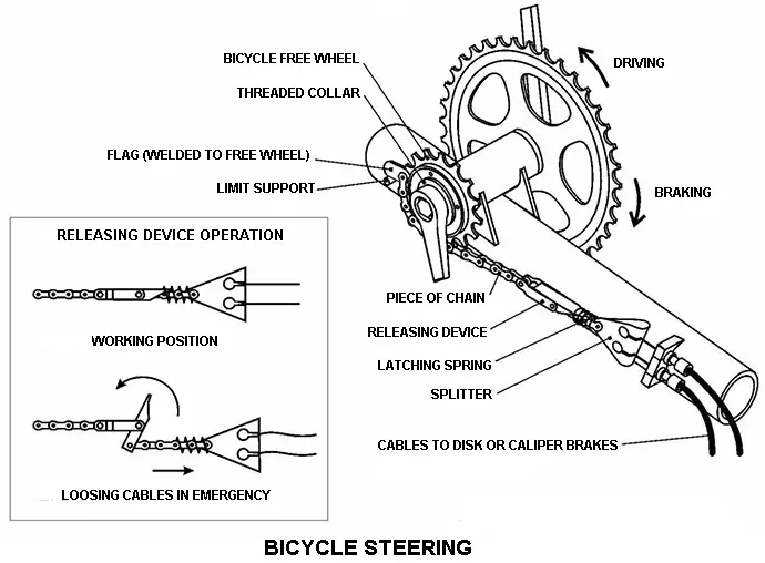
In these types of steering systems, the rare wheel is fixed while the front wheel is steered. For a safe turning, it is essential that the two wheels must roll about a point. In this case, the perpendicular of the front wheel when produces cut the addition of the perpendicular to the rear wheel and that point is saying as the instantaneous center.
#2 Turntable or Centre Pivot Steering
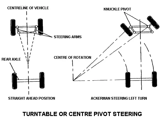
In a four-wheel vehicle, the front two wheels are mounted on the axle and the axle, in turn, is fixed to a turntable having a single pivot.
When the front wheels are turned, the whole front axle is turned about the central pivot. In this case, also the perpendiculars of all the wheels meet at a point during any turn, so that the turning is safe and the wheels roll freely.
This type of steering system is commonly used in horse-drawn coaches and trails. This is unsuitable for automobile vehicles because it is unstable at high speeds. Moreover, a center pivot steering arrangement requires a lot of space and because for the whole axle to turn.
#3 Ackerman Steering or Side Pivot Steering
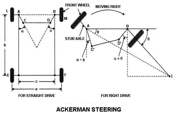
This is the modern steering layout of almost all automobiles. In this type of steering system, each front wheel is turned individually about the side pivot.
The front axle is pivoted on either side of the axles. And as the stub axles, the wheels are mounted. The stub axles are turned by steering arms connected to the tie rod.
The steering arms are not parallel but are inclined. The line produced from the inclined arms will meet at the center of the rear axle line forming an angle called the “Ackerman Angle”.
To obtain a good alignment it is necessary to understand the following factors,
- Camber (Wheel rake or Camber angle).
- Caster.
- King Pin inclination.
- Toe-in.
- Toe-out.
Camber
The angle between the centerline of the tyre and the vertical line, when viewed from the front of the vehicle, is known as camber. When the wheels are tilted outwards at the top is called positive camber, and if titled inward at the is called negative camber. An equal camber angle is provided on both the front wheels.
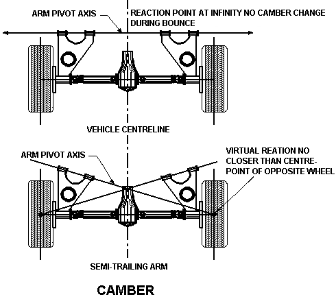
With the positive camber, wheels become verticle under load on the tyre will have full contact with the road, hence the tyre wear will be uniform. If the positive camber is excessive then tyres outer edge will rear will wear out faster. If the negative camber is excessive the tyres inner edge will wear out faster.
Unequal camber on both the front wheels will result in wheels vibration at low speed. Older models have considerable camber. Present-day cars use improved design and materials they have very little camber. The camber should not exceed 2°. The camber on modern vehicles is adjusted by means of an eccentric cam in the control arm shaft.
Caster
The Kingpin axis or steering axis may be tilted forward or backward from the vertical line. This tilt is known as Caster. Caster Angle: The caster angle is the angle formed by the forward or backward tilt of the steering axis from the vertical when viewed from the side of the wheel.
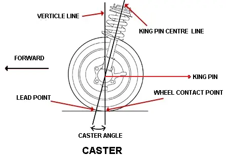
A backward tilt is known as a positive caster and a forward tilt is known as a negative caster. If the caster is not equal on both sides it will cause the vehicle to pull to the side of the wheel having a lesser caster angle. The caster angle in modern vehicles varies from 2° to 8°.
Purposes of Caster
- To maintain directional stability and control.
- To increase steering stability.
- Reduce drives effort to turn the vehicle.
King Pin Inclination
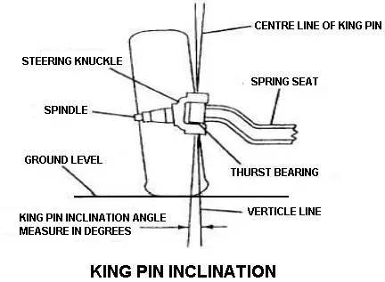
The angle between the vehicle line and center of the kingpin or steering axis, when viewed from the front of the vehicle, is known as Kingpin inclination.
The Kingpin inclination in modern cars varies from 7° to 8°. It must be equal on both sides. It is greater on one side than the other, the vehicle will tend to pull to the side having a greater angle.
The main functions of Kingpin inclination are as follows,
- It helps in self-centring of wheels after taking a turn.
- To provide directional stability.
- It reduces steering effort.
Toe-in
Front wheels are slightly tilted inward at the front of the distance between the front wheels at the front (A) is less than the distance at its rear (B) measured at the height of the hub level and at the center of the wheel tread.
The difference in its distance is ‘Toe-in’ (B-A). it is usually 2 to 3 mm. The purpose of the toe-in is to overcome the bad effect of camber. The toe-in is adjusted by tie-rod ends.
Toe-out
Whenever the vehicle is taking a turn with Ackerman steering geometry the inner wheel turn more degrees than the outer wheel so that the perpendiculars of all four wheels at a point when produced. This point is called the instantaneous center so that all the wheels roll very easily without scuffing.
Types of Steering System Depending Upon the Leverage
There are two types of steerings depending upon the leverage provided between the road wheel and the steering wheel and also the number of shocks and vibrations transmitted from the road wheels to the steering wheels, namely,
- Reversible steering.
- Irreversible steering.
Reversible Steering
Reversible steering is one in which the gear ratio is 1:1. For example bicycle or scooter steering. In gear case, any angular movement of the handle causes the same angular movement to the wheel and the wobbling or vibrations of the wheel are faithfully transmitted to the steering handle. This arrangement is suitable for only bicycles, motorcycles, scooters, etc.
Irreversible Steering
Here gear reduction between and wheels and the steering wheel is very high. Ex-In road rollers it is about 40:1.
Here very high gear reduction is necessary. Because the load carried on the wheel is very high. With this type of steering, there will not be any transmission of notion due to vibration of the wheel from road wheels to steering wheels.
Steering Gears
If the steering wheel is connected directly to the steering linkage it would require a great effort to move the front wheels. Therefore, to assist the driver a reduction system is used. The Steering gear is a device for converting the rotary motion of the steering wheel into the straight-line motion of the linkage with a mechanical advantage. The steering gears are enclosed in a box called the steering gearbox.
Types of Steering Gears
Following are the eight important steering gears:
- Recirculating ball steering gear.
- Rack and pinion steering gear.
- The Worm and sector steering gear.
- Worm and roller steering gear.
- Worm and ball bearing nut steering gear.
- Cam and roller steering gear.
- The Cam and peg steering gear.
- Cam and double lever steering gear.
1. Recirculating Ball Steering Gear
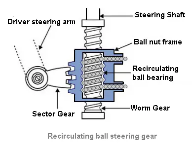
The circulating ball gear is similar to the worm and ball bearing not steering gear. The balls are contained in half nut and a transfer tube. As the cam or worm rotates, the balls pass from one side of the nut to the transfer tube to the opposite side. As the nut cannot turn, and movement of the balls along the track of the cam carries the nut allowing with it and rotates the rocker shaft.
2. Rack and Pinion Steering Gear
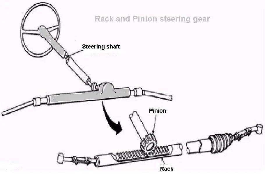
In the rack and pinion steering gear, a pinion is mounted on the end of the steering shaft. It engages with the rack which has a ball joint at each end to allow for the rise and fall of the wheels.
The roads connect the ball joints to the stub excels. The rotary movement of the steering wheel turns the pinion which moves the rack sideways. This movement of the rack is converted into wheels.
3. Worm and Sector Steering Gear
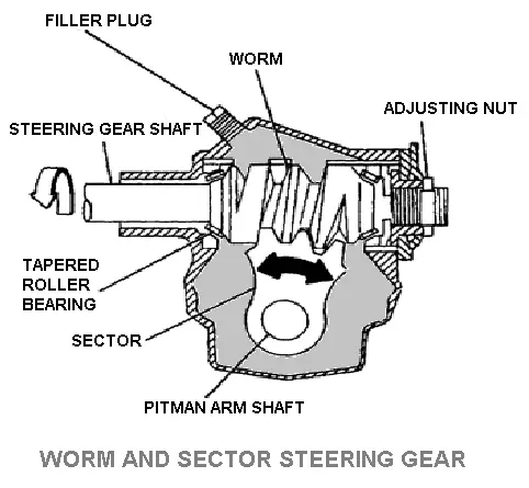
In the worm and sector steering gear, the worm on the end of the steering shaft meshes with a sector mounted on a sector shaft. When the worm is rotated by rotation of the steering wheel, the sector also turns rotating a sector shaft. Its motion is transmitted to the wheel through the linkage.
Note that 6the sector shaft is also known as pitman arm shaft, pitman shaft, roller shaft, steering arm shaft, cross shaft.
4. Worm and Roller Steering Gear
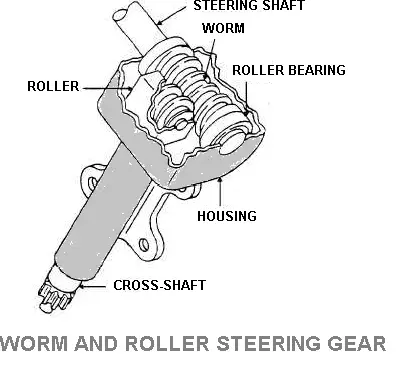
In the worm and roller steering gear, a two-toothed roller is fastened to the sector or roller shaft so that it meshes with the threads of the worm gear or shaft at the end of the steering shaft or tube.
When the worm shaft is turned is it causes the roller to move in an arc so as to rotate the roller shaft, and at the same time turn on the pin connecting it to the shaft. The roller is mounted on a ball bearing.
The worm shaft is mounted on a bearing designed to resist both radial and end thrust. This type of steering gear is widely used in American passenger cars.
5. Worm and Ball Bearing Nut Steering Gear
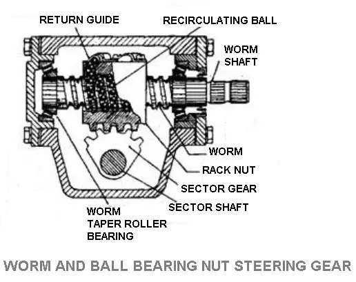
In the worm and ball bearing nut steering gear, a ball nut is mounted on the worm of the steering shaft. The worm and the nut have mating spiral grooves in which steel balls circulate to provide a frictionless drive between the worm and nut.
Two sets of balls are used, with each set operating independently of others. A ball return guide is attached to the outer surface of the nut. When the steering shaft is turned to the left or right, the ball nut is moved up and down by the balls which roll between the worm and nut.
A sector gear mounted on the sector shaft meshes with the ball nut, so that it gets motion by the ball nut.
6. Cam and Roller Steering Gear
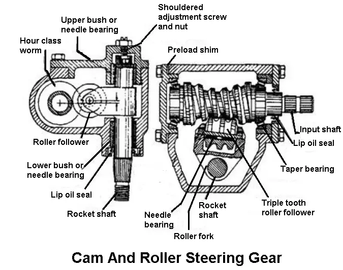
In the cam and roller steering gear, a cam meshes with the roller. As the cam rotates, the roller is compelled to follow the cam and in doing so causes the rocker shaft to rotate, thus moving the drop arm.
The contour of the cam is designed to mesh with the arc made by the roller so maintaining a constant depth of mesh and evenly distributing the load and wear on the mating parts.
7. Cam and Peg Steering Gear
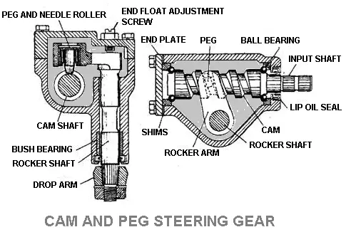
In the cam and peg steering gear attached to the rocker arm is a tapered peg that engages in the cam. When the cam rotates, the peg moves along the groove causing the rocker shaft to rotate.
8. Cam and Double Lever Steering Gear
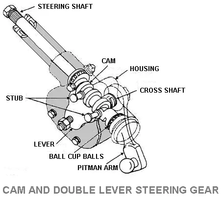
In the cam and double lever steering gear, a special worm called a cam, replaces the worm used in the two types of worm and sector steering gear and worm and roller steering gear.
The cam is cylindrical in shape, its actuating part being a groove of the variable pitch made narrower at the center than at the end. This provides non-reversibility in the center part of the cam where most of the car steering takes place.
The twin levers are mounted on the cross shaft and are located so that the stubs engage the cam from the side. When the cam is turned, the stubs move along the cam groove to cause the lever to swing through an arc and thus turning the cross shaft.
Conclusion
That’s it, thanks for reading. If you have any questions about the “steering system and its types” ask in the comments. If you like this article please share it with your friends.
Subscribe to our newsletter. It’s totally free.
Download PDF file of this article:
External links:
- Read more about car steering system in Wikipedia
- Steering system (PDF) by Researchgate.net
Useful Links:
Great overview of steering systems! I found the diagrams really helpful in understanding the different types and their functions. It’s fascinating how each part contributes to the overall driving experience. Thanks for sharing!
Great post! I learned a lot about the different types of steering systems and their components. The diagrams were especially helpful in visualizing how everything fits together. Thank you for making such complex information easy to understand!
Thank you! I’m glad the diagrams helped and that you found the information clear and useful. 😊
THANK YOU.
Welcome.
Please kindly send me the pdf documents
The PDF file has been sent to your inbox.
Please guys help me to download this PDF
The PDF file has been sent to your inbox.
Please give us pdf download format
Hi there! Now you can download the PDF of this article. Thanks for reading.
Thank so much I like it it’s good
You’re most welcome.
Very insightful. Many thanks.
You’re welcome
Thank for this articles
You,re most welcome.
You’re most welcome.