In this post, you learn about what is coal handling plant it’s layout, requirement for coal handling plant, method of coal storage and fuel-burning, ash handling and it’s treatment.
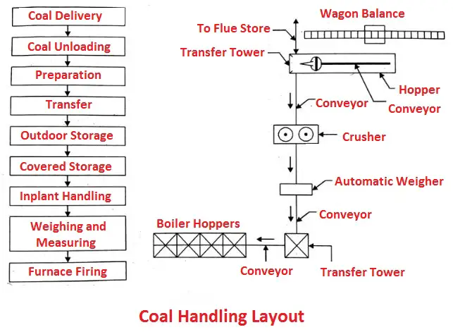
Coal Handling Layout
A simple coal handling layout as shown in the figure. It consists of
- Coal delivery
- Coal unloading.
- Preparation
- Transfer
- Outdoor storage.
- Covered storage.
- Inplant handling.
- Weighing and measuring.
- Furnace firing.
Requirements of Coal Handling Layout
- Low maintenance.
- Higher reliability.
- Should be simple and sound.
- It should require minimum operatives.
- Easy and smooth in operation.
- Should supply right quality of fuel in the right time in the right quantity.
- Should have minimum wear in running the types of equipment.
Coal Handling Methods
Following are the different coal handling methods are used:
- Transportation by sea or river
- Rail
- Ropeways
- Road
- Pipeline
1. Transportation by Sea or River
The coal can be transported from the mines to the power stations by means of ships or large boats through the ocean or river. The unloaded coal from the ship can be either sent to the storage yard or directly to the conveyor system which directly to the combustion chamber hopper.
2. Transportation by Rail
In this case, the railway is used to transport the coal from the mines directly to the power stations, most of the thermal power stations will receive the coal from rail transport. The coal from the railway wagon is taken to the power station and is either delivered to the storage yard or close to the point of consumption.
3. Transportation by Ropeways
It is the most efficient method of transporting coal from the mine to the power station. It is particularly used when the distance between the power station and mine is less than 10 km.
The major advantage of such a system is, it supplies the coal continuously and free from worker’s strike which is common with rain transport.
4. Transportation by Road
The coal can be transported from mines to the power plant by means of trucks, tippers, tractors etc., through road, but it is used only for small capacity power stations. The major advantage of this type is that the coal can be carried directly into the powerhouse up to the point of consumption.
5. Transportation by Pipeline
In this method, the coal in the form of slurry is directly supplied from the remote mines to the strategically located thermal power plants through pipelining. This method is the most efficient one. It supplies a large quantity of coal continuously without any problem and loss. This system is costlier than all other systems but most economical in operation.
Read also:
- Thermal Power Plant: Layout, Working, Elements, Advantages and More
- Power Plant: Types, Factors, Choices and Terminology Used in Power Plant
- What is Power Plant Economics? It’s Cost of Power Generation and Calculation
Various Stages in Coal Handling
The various stages in coal handling are :
1. Coal Delivery
From the supply points, the coal may be delivered to the power station through rail, road, river or sea. Plants situated near the river or sea may make use of ships or boats. The stations which cannot make use of ships or boats may be supplied either by rail or trucks.
If the coal mine is nearer to the plant or when the necessary railway facilities are not available, then the coal is supplied by truck. In case rail transport is to be adopted, the necessary siding for receiving the coal should be made near the station.
2. Unloading
The coal is unloaded by using proper unloading equipment. The use of unloading equipment in the plant depends upon the type of out-plant handling mode as road, rail or ship. If the coal is delivered by trucks, there is no need of unloading device as the trucks may dump the coal to the outdoor storage. The coal is easily handled if the lift trucks with scoop are used.
When the coal is transported by sea, the unloading is carried out by portable conveyors, coal accelerators, coal towers, unloading bridges or by safe unloading boats.
3. Preparation
If the coal when delivered is in the form of lumps (not of proper size), the coal preparation may be carried out by :
- Breakers
- Crushers
- Sizers
- Dryers
- Magnetic separators.
4. Transfer
After preparation, the coal is transferred to the final storage point from where it is discharged to the fixing equipment.
Following equipment are used for the transfer of coal:
- Belt conveyors
- Screw conveyors
- Vee bucket elevator
- Pivoted bucket conveyor
- Grab bucket conveyor
- Flight conveyor
- Skip hoists
- Mass flow conveyor
- Chutes.
4.1 Belt Conveyors
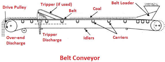
A belt conveyor is a very suitable means of transporting the coal in large quantities over large distances as shown in the figure. It consists of an endless belt running over a pair of end pulleys and supported by a series of rollers called idlers provided at regular intervals.
4.2 Screw Conveyor
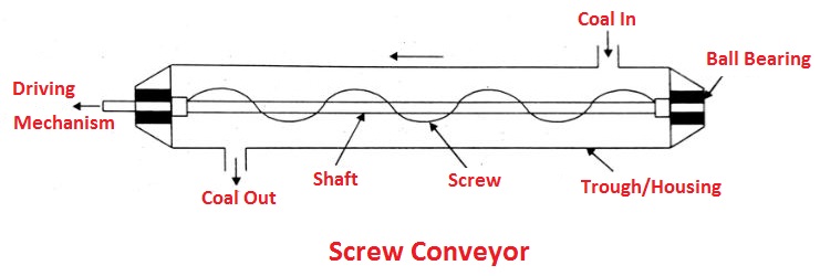
It consists of an endless helicoid screw fitted to a shaft as shown in the figure. The driving mechanism is attached to one end of the shaft and the other end of the shaft is supported in the attached ball bearing. The screw while rotating it transfers coal from one end to the other end.
4.3 Vee Bucket Elevator
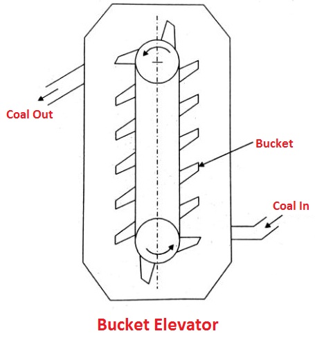
This conveyor consists of vee buckets suspended over an endless chain driven by a motor as shown in the figure. The conveyor loaded by passing below a coal pocket and discharged at the other end.
4.4 Pivoted Bucket Conveyor
It consists of malleable iron buckets suspended over an endless chain driven by a motor. The conveyor is loaded by passing below a crusher and discharged into the bunker by a tripping device.
4.5 Grab Bucket Conveyor
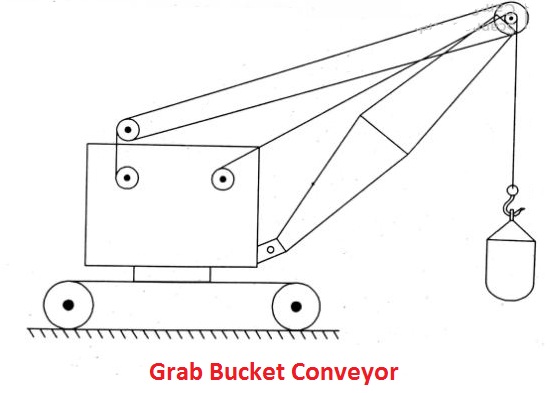
It is in the form of a hoist which lifts and transfers the coal on a single track from one point to another as shown in the figure. The capacity of these units is about 50 tonnes/hr.
4.6 Flight Conveyor
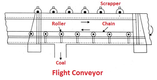
It is generally used for the transfer of coal when filling of the number of storage bins situated under the conveyor is required. It consists of one or two strands of chain, to which steel scraper are attached. The scraper scrapes the coal through a trough and the coal is discharged in the bottom of the trough as shown in the figure.
4.7 Skip Hoist
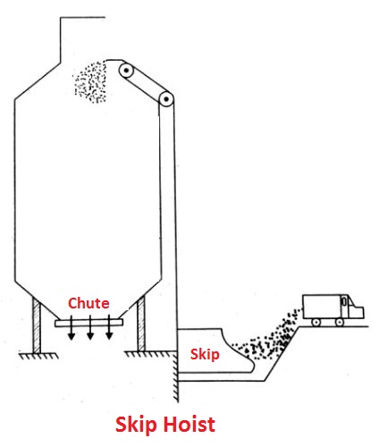
It is used for high lifts and handling is non-continuous. It is used for both coal and ash handling as shown in the figure.
5. Storage of Coal
It is very essential that an adequate quantity of coal should be stored. The coal storage gives protection against the interruption of coal supplies when there is a delay in the transportation of coal.
Coal storage requirements should be considered when selecting a site for storage.
The coal storage requires the following:
- No stranding of water near the storage area.
- Proper drainage ditches should be provided.
- Storage should be solid and not loose or porous.
- Handling cost should be minimum.
- The area should be protected against the fire.
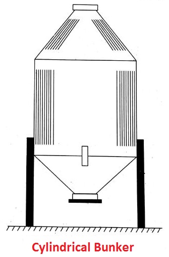
Live storage is covered storage provided in plants, sufficient to meet the one-day requirement of the boiler. The bunkers made up of steel or reinforced concrete is used to store the coal as shown in the figure. From here coal is transferred to boiler gates.
6. Inplant Handling
It refers to one of the following:
- Coal handling between the final storage and the firing equipment.
- A conveying system to feed coal from any bunker section to any fixing unit and to move coal from one bunker section to another.
Inplant handling may include conveyors to transfer the coal, weigh lorries, hoppers and automatic scales to record the quantity of coal delivered to the furnace.
7. Weighing and Measuring
To weigh the quantity of coal the following equipment may be used :
- Weighbridges
- Belt scale
- Weigh lorry
- Automatic scale.
8. Furnace Firing (Fuel Burning)
Efficient combustion of fuel in the combustion chamber and efficient transfer of heat energy to water for steam generation is necessary for economical functioning of the power plant.
Classification of Fuel Firing
The two common methods used for burning the coal (solid fuel) are:
- Stoker firing :
- Travelling grate stoker
- Chain grate stoker
- Bar grate stoker
- Spreader stoker
- Travelling grate stoker
- Pulverised fuel firing :
- Single retort stoker
- Multi-retort stoker
Methods of Coal Storage
The coal can be stored by using one of the following methods to reduce the chances of oxidation and combustion :
- Stocking the coal in heaps
- Underwater storage
1. Stocking the Coal in Heaps
Following steps are used while stocking the coal in heaps:
- The ground used for stocking the coal should be dry and level. Generally, the concrete-floored area is used to prevent the flow of air from the bottom.
- The coal is piled on the ground up to 10-12 m height.
- During storage of coal in heaps, the coal should be compacted in a layer of 15 to 30 cm in thickness by means of bulldozers and rubber-tired scrapers.
- This effectively prevents air circulation in the interior of the pile.
- Then the pile top should be given a gentle slope in the direction in which rain may be drained off so that the water will be removed. But it should not be drained so rapidly as to cause serious washing.
- The sealing of the stored pile may be done to avoid the oxidation of coal after packing an air-tight layer of coal.
2. Under Water Storage
The possibility of slow oxidation and spontaneous combustion may be totally eliminated by storing coal underwater. The dock basins can be used for storing the coal under-water.
Methods of Fuel Burning
1. Stoker Firing
A stocker is an electric-powered fuel feeding mechanism and great. The stokers are classified into:
- Overfeed stokers
- Underfeed stokers.
Advantages of Stoke Firing
- A cheaper grade fuel can be used.
- Higher efficiency is achieved.
- Less smoke production.
- Greater flexibility in operation.
- Less building space is required.
- Can be used for small or large boiler units.
- Reliable.
- Low maintenance charges.
- Reduction auxiliary plant.
- Low capital investment.
Disadvantages
- Construction is complicated.
- For larger unit construction cost becomes higher.
- Troubles due to slagging and clinkering.
- Sudden variation in demand cannot be met effectively.
1.1 Overfeed Stoker
The principle operation of overfeeding stoker is shown in the figure. The coal is supplied on the top surface of the grate. The ignition plane lies within green coal and incandescent coke. The air enters from the bottom of the grate under pressure. The air is heated while passing and cools the ash and grate and comes in contact with incandescent coke.
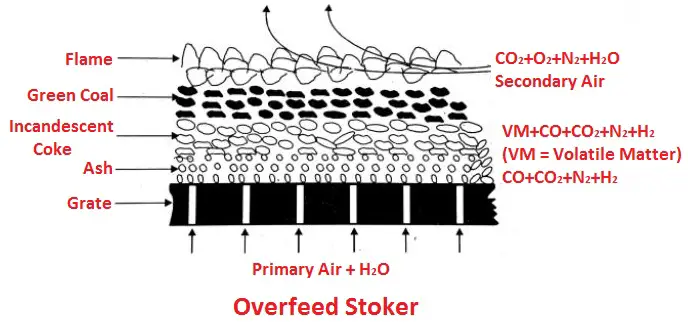
At this stage, the oxygen reacts with carbon to form carbon dioxide and the water vapour entering with the air reacts with coke to form CO2, CO and free H2. Upon further travels, through the incandescent region, some of the CO reacts with coke to form CO. Hence no free O2 will be present in the gases leaving the incandescent region.
The raw coal continuously supplied on the surface of the coke bed losses its volatile matter by distillation due to the hot gases diffusing through the coke bed. Therefore the ignition zone lies directly below the raw fuel undergoing distillation.
To burn the combustible gases, additional secondary air must be fed at high speed into the furnace to supply the needed oxygen. The combustible gases then burn in the furnace.
1. Chain Grate Stoker
It consists of a flexible endless chain which forms a support for the fuel bed. The chain travels over two sprocket wheels one at the front and one at the rear of the furnace. The front sprocket is connected to a variable speed drive mechanism.
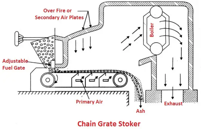
The coal bed thickness is maintained all the time by index plate. This can be regulated either by adjusting the opening of fuel grate or by controlling the speed of the stoker drive motor.
The primary air enters from the bottom of the grate as shown in the figure is divided into several compartments and secondary air is supplied from the top to have complete combustion of the fuel. The rate of burning of this stoker is 200 to 300 kg/m² per hr when forced drought is used.
Advantages
- Simple in construction.
- Low initial cost.
- Low maintenance charge.
- Self-cleaning of stoker.
- The heat release rate can be controlled by the speed of the chain.
- Give high heat release rates/unit volume of the furnace.
2. Spreader Stoker
In this case, the coal is not fed into the furnace by means of the grate. The function the grate is only to support the bed of ash and move it out of the furnace.
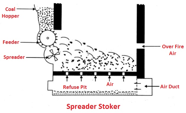
From the coal hopper, the coal is fed into the path of a rotor by means of a conveyor and is thrown into the furnace by the rotor and is burnt in suspension. The air for combustion is supplied through the holes in the grate as shown in the figure. The secondary air to have complete combustion of fuel is supplied through nozzles located above the coal bed. The spreader stokers can burn any type of coal.
Advantages
- Wide variety of coal can be burnt.
- Simple in operation and easy to light up.
- High-temperature preheater can be used.
- Low operating cost.
- Volatile matter can burn very easily.
- Reduced difficulties due to clinkering.
1.2 Underfeed Stoker
An underfeed stoker is suitable for burning the semi-bituminous and bituminous coals. The principle operation of underfeeds stoker as shown in the figure. An air entering through the holes in the grate comes in contact with the raw coal (green coal).
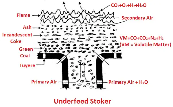
Then it passes through the incandescent coke where reactions similar to overfeed system takes place. The gases generated then pass by a layer of ash. The secondary air is provided to burn the combustible gases.
The produced gases then pass through a layer of ash. Secondary air is supplied to burn combustible gases.
1. Multi-retort Underfeed Stoker
The simple construction of a multi-retort underfeed stoker is shown in the figure. This stoker consists of a series of sloping parallel troughs formed by tuyers stocks. These troughs are called as retorts. Under the coal hopper, feeding rams reciprocate back and forth.
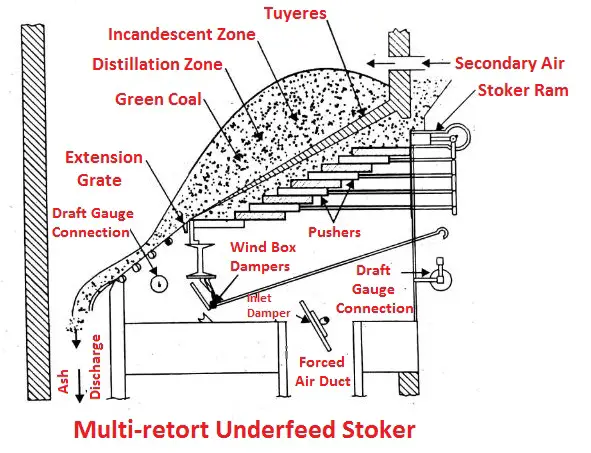
The ram pushes the coal from the hopper falls into space vacated by the rain during the outward stroke. On the inward stroke, the ram forces the coal into the retort, thereby slowly move the entire down the length of the stoker.
At the rear of the stoker, the partly burned fuel bed moves into an extension grate arranged in sections. The sections also oscillate parallel to the fuel bed movement. The sharp slope of the stoker aids in moving the fuel bed.
Tilting the damp plate at long intervals deposits the ash in the ashpit below. Primary air is supplied below the stoker into the fuel bed by means of forced air duct and the secondary air is supplied for complete combustion of the coal from the top of the coal bed.
Pulverised Fuel Firing (Pulverised Fuel Handling System)
In an inflated fuel firing system, coal is reduced to a fine powder with the help of grinding the mill and is then projected into the combustion chamber with the help of hot air current. The amount of air required (secondary air) to complete the combustion is supplied separately to the combustion chamber.
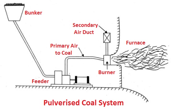
The resulting turbulence in the combustion chamber helps for uniform mixing of fuel and air and thorough combustion. The primary air is used to carry the coal and dry it before entering the combustion chamber as shown in the figure. The efficiency of pulverised fuel firing system depends on the size of the powder.
Advantages
- Any grade of coal can be used.
- Rate of feed of the fuel can be regulated properly.
- Higher capacity to meet peak loads.
- Complete combustion of the fuel.
- No ash handling problems.
- Free from clinker problem.
- Free from erosion.
- No moving part is subjected to high temperature.
- Less furnace volume is required.
Disadvantages
- High initial cost.
- A lot of fly-ash in the exhaust.
- Possibility of an explosion is more.
- Skilled operators are required.
- Separate coal preparation plant is necessary.
- Nuisance is created due to the emission of fine dust.
Systems of Pulverised (Fuel) Coal Firing (Pulverised Fuel Handling Systems)
Following are the systems of pulverised coal firing:
- Unit system or direct system
- Central system or bin system.
1. Unit System
In this system, the raw coal from the bunker is supplied to the feeder as shown in the figure. Hot air is passed by the feeder to dry the coal.
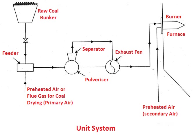
The dry coal is then transferred to the pulverising mill to pulverise the coal. The primary air is supplied to the mill to carry the pulverised coal to the burner where the secondary air is mixed to have complete combustion of the fuel.
Advantages
- The layout is simple.
- Easy in operation.
- Less space is required.
- Cheaper.
- Allows direct control of combustion.
- Low maintenance charge.
- No complex transportation.
2. Central System
A central system as shown in the figure. The raw coal from the bunker is supplied to the feeder where the primary air drives the coal and transferred to the pulverising mill.
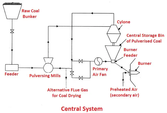
The pulverised coal from a mill is transferred through alternative flue gas to the cyclone separator, where the coal is separated and flue gas is sent back to the mill. The coal is then supplied to the burner feeder from where it is mixed with primary air and supplied to the burner for the combustion.
Advantages
- Good control on coal fineness.
- Less labour is required.
- The burner can operate independently from the coal preparation.
- Low power consumption.
- The pulverised mill may work on constant load.
Pulverisation of Coal
The pulverisation of coal means coal is powdered to the required size for the burner for the combustion of a fuel. The efficiency of a pulverised fuel firing system depends mostly on the size of the powder.
The pulverised coal is obtained by grinding the raw coal in pulverising mill. The various pulverising mill used for pulverisation as follows:
- Ball mill
- Hammermill
- Bowl mill
- Ball and Race Mill.
- Pulverisation coal involves the following:
- Drying the coal
- Grinding the coal
- Separation of desired size coal particles.
Advantages of Pulverised Coal
- Easy in handling a variety of coal.
- Easy in burning variety of coal.
- Combustion requires less amount of air.
- Increased combustion efficiency.
- No clinker problem.
- Higher temperature can be achieved.
- Combustion rate can be adjusted very easily.
- Higher capacity to meet peak loads.
Disadvantages
- Higher initial cost.
- Lot of fly-ash in the exhaust creates a problem.
- Possibility of an explosion is more.
- Skilled operators are required for operation.
- High nuisance due to emission of fine dust.
1. Race and Ball Mill
A simple arrangement of race and ball mill is shown in the figure. It consists of upper and lower races and filled with steel balls in between them. The raw coal from the feeders passes between the rotating races again and again until it has been pulverised to the desired degree of fineness. The pulverization is completed by crushing, impact and attrition between grinding surfaces.
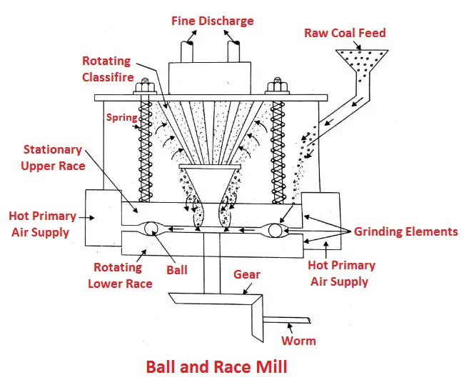
Hot air is supplied by forced drought fan to pick up the powdered coal dust and enters into the classifier where required size particles are discharged to the burner and oversized particles are thrown back to mill for further pulverisation.
Ash Handling
A huge quantity of ash is produced in the central station, sometimes as much as 10 to 20% of the total quantity of coal burnt in a day. Therefore hundreds of tonnes of ash may have to be handled every day in large power plants. Handling of ash includes:
- Its removal from the furnace.
- Loading on the conveyors and delivery to fill or dump into the sump, from where it can be disposed of.
Ash Handling Systems
For ash handling, the modern ash handling systems may be used, these are :
- Gravity system or Hydraulic system.
- Pneumatic or Vacuum system.
- Electrostatic precipitation (ESP) system.
- Mechanical dust collector.
1. Gravity System or Hydraulic System
In this system, ash is carried with the flow of water with high velocity through a channel and finally dumped in the sump. This system is divided into :
- Low-pressure system
- High-pressure system.
1. Low-Pressure System
A simple construction of such system as shown in the figure. In this system, a trough or drain is provided below the boilers and the water is made to flow through the trough. The ash directly falls into the troughs and is carried away by the water to the sumps.
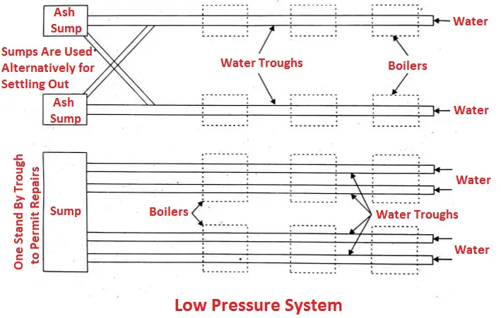
In the sump, the ash and water are made to pass through a screen so that water is separated from ash. This water is pumped back to the trough for reuse and ash is removed to the dumping yard. The ash carrying capacity of such a system is 50 tonnes/hr to a distance of about 500 metres.
2. High-Pressure System
In this system, the hoppers below the boilers are fitted with water nozzles at the top and on the sides as shown in the figure. The top nozzles extinguish the ashes while the sides provide the driving force for the ashes. Cold ashes are carried to the sump through the trough.
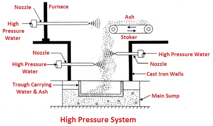
The water is again separated from each recirculated. The ash carrying capacity of such a system is as large as 120 tonnes/hours and the distance covered is about 1000 m.
Advantages of Gravity System
- The system is clean and healthy.
- It can also handle molten ash.
- The working parts are not exposed to ash.
- It is dustless and totally closed.
- Discharges the ash to a considerable distance,
- High ash carrying capacity.
2. Electrostatic Precipitators (A Dust Collector) System
It is also called as “Cottrell precipitators”. The basic elements of an electrostatic precipitator as shown in the figure.
- Source of high voltage
- Ionizing and collecting electrodes
- Dust-removal mechanism
- Shell to house the elements.
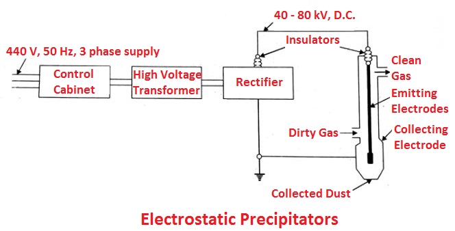
The precipitator has two sets of electrodes, insulated from each other, that maintain an electrostatic field between them at high voltage. The field ionizes dust particles that pass through it attracting them to the electrode of opposite charge. The high voltage system maintains a negative potential of 30,000 to 60,000 volts with the collecting electrodes grounded.
The collecting electrodes have a large contact surface. Accumulated dust falls of the electrode when it is rapped at a regular interval mechanically. A wet type of this unit removes dust by a water film flowing down on the inner side of the collecting electrode.
Advantages
- Effective removal of small particles like smoke, mist and fly-ash.
- Easy operation.
- The draught loss is quite less.
- Most effective for high dust loaded gas.
- Maintenance cost is minimum.
- The dust is collected in dry form is removed either dry or wet.
Disadvantages
- Space requirement is more.
- Necessary to protect the collector from sparking.
- High running cost.
- High capital cost.
Feed Water and its Treatment
For thermal power plants, water is one of the most important raw materials. In most of the cases, water used for thermal power plants contains impurities which must be treated before use. All-natural waters-even rain, snow, hail, treated municipal supplies contain impurities in one form or the other.
The presence of the impurities in the water may cause the following problems:
- Scale formation
- Corrosion
- Carry over
- Embrittlement.
Following different methods can be adopted for water treatment :
- Mechanical treatment:
- Sedimentation
- Coagulation
- Filtration
- Interior painting
- Thermal treatment:
- Deaeration
- Distillation by evaporators
- Chemical treatment.
- Demineralisation.
- Blow down.
Mechanical Treatment
1. Sedimentation
In this process, the water is allowed to stand at a standstill in big tanks. So that solid matter settles down. These solid matters are then removed periodically or continuously. The clear water is then drained out from the tank surface.
2. Coagulation
In this process some coagulants like aluminium sulphate, sodium aluminates are added to the impure water which on reaction removes the minute colloidal suspensions easily.
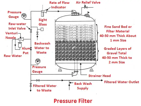
3. Filtration
It consists of passing the water through filters such as a bed of fine sand and then a layer of gravels etc., as shown in the figure. The suspended matter adheres to the filter material leaving the water clear at it drains from the bottom. The beds must be washed periodically to remove the dirt that collects in the voids of the filter material. In case of pressure filter, the water is forced through the filter by means of a pump whereas in gravity filter the water flows by gravity.
Read also:
- Thermal Power Plant: Layout, Working, Elements, Advantages and More
- Power Plant: Types, Factors, Choices and Terminology Used in Power Plant
- What is Power Plant Economics? It’s Cost of Power Generation and Calculation
That’s it thanks for reading. If you have any question on “Coal Handling Plant” let me know in the comments. Share this article with your friends.
Sir I read your technical article and was very impressed.
Thanks for your feedback.