In this post, you’ll learn about What is Compound Steam Engine and how it works. With its Classification, Arrangement of Cylinders and Advantages with PDF and More.
Compound Steam Engine and It’s Types
The scientists and engineers, working for the improvement of simple steam engines, thought of various methods. One of the methods was to use high-pressure steam. They faced the following difficulties in expanding high-pressure steam in a single cylinder:

- The steam, when allowed into a cylinder, comes in contact with relatively cold cylinder walls which cause initial condensation.
- When the steam is expanded down to the condenser pressure, there is a greater range of pressure difference. This causes a larger temperature range in the cylinder.
- Due to the greater range of pressure difference, the ratio of expansion is large.
- The stroke of the piston is large because of the large rate of expansion.
To overcome these difficulties, the expansion of steam is divided into stages, each stage in a separate cylinder. In this method, high-pressure steam is first partially expanded in a high-pressure cylinder and then terminated in a low-pressure cylinder, where expansion is complete.
This method reduces the ratio of expansion in the cylinder, which also results in reduced stroke length. Further, it decreases the temperature range in each cylinder. This lead to the development of compounds engines.
Read Also: Steam Condenser: Types, Working, Advantages and More
Arrangement of Cylinders
We have already discussed that a steam engine, in which the expansion of steam takes place, in more than one cylinder, is known as a compound steam engine. The cylinder, which holds the high-pressure steam, is known as high pressure (H.P.) cylinder.
The steam after expanding in the high-pressure cylinder exhausts into a larger cylinder known as low pressure (L.P.) cylinder. In this cylinder, the last stage of expansion is done. The L.P. cylinder generally exhausts into a condenser.
This is why compound steam engines are usually the type of condensate. But they may be non-condensing also. If the expansion of steam takes place in three cylinders the engine is called a triple expansion engine. Similarly, if expansion is done in four cylinders, it is called a quadruple expansion engine.
In the case of triple expansion engines, the first stage of expansion is operated in H.P. cylinder, intermediate expansion occurs in the intermediate pressure (I.P.) cylinder, and the final expansion is completed in the L.P cylinder. In the quadruple expansion engine, the intermediate expansion is carried out in two I.P. cylinders.
Note:
The high-pressure cylinder is, generally, of a smaller size than the low-pressure cylinder.
Classification of Compound Steam Engines
The compound steam engines may be classified according to the arrangement of cranks, and the angles between them. Two-cylinder compound engines are generally classified as:
- Tandem type compound engines
- Woolf type compound engines
- Receiver type compound engines
1. Tandem Type Compound Engines
In this engine, the cylinders (H.P. and L.P.) have a common piston rod working on the same crank as shown in the figure.
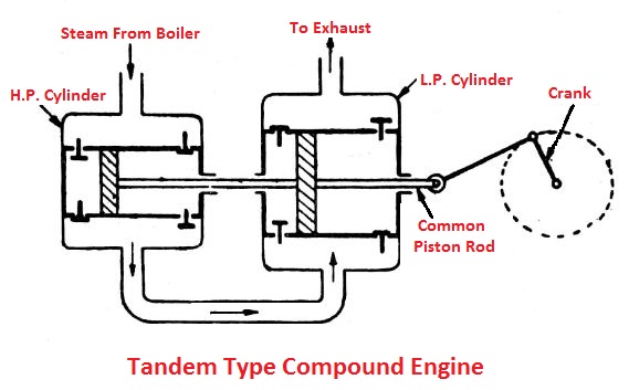
In a tandem type compound engine, the steam from the boiler is admitted to one side of the high-pressure cylinder. The steam coming out of this cylinder goes directly into the low-pressure cylinder. Since both the pistons are at the end of their strokes. Therefore these cylinders can be considered to be cranked from 0° to each other.
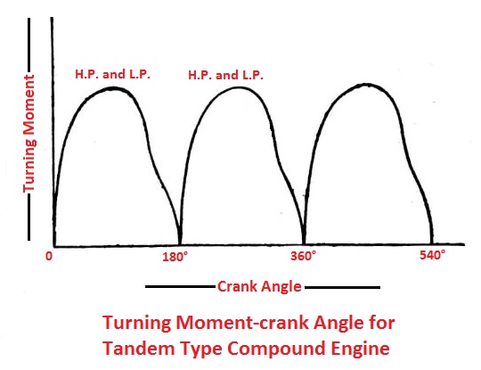
The figure shows the graph of turning moment on the crankshaft versus crank angle. It may be noticed from the graph that their cycle is in phase, therefore maximum turning moment on the crankshaft due to each cylinder will act the same time. This is the disadvantage of this type of compound engine, as a larger flywheel is required to overcome these fluctuations.
2. Woolf Type Compound Engines
In this engine, the two cylinders (H.P. and L.P.) have different piston rods attached to two different cranks set of 180° to each other. These cranks are cast in the same crankshaft as shown in the figure.
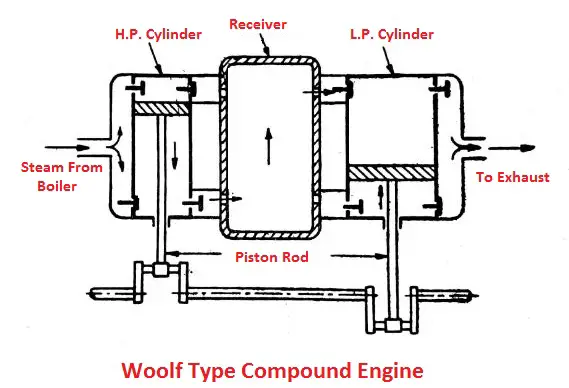
In a woolf type steam engine, the steam from the boiler is admitted to one side of the high-pressure cylinder. The exhaust steam coming out of this cylinder goes directly into the low-pressure cylinder.
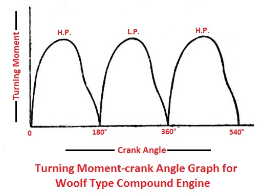
The figure shows the graph of turning moment on the crankshaft versus crank angle. As the cranks are 180° apart, the two cycles are in phase and there is a large variation in the turning moment on the crankshaft, which requires a large flywheel. Thus the Woolf type compound engine has the same disadvantage as the Tandem type compound engine.
3. Receiver Type Compound Engines
In this engine, the two cylinders (H.P. and L.P.) have different piston rods attached to two different cranks set at 90° to each other. These cranks are cast in the same crankshaft as shown in the figure.
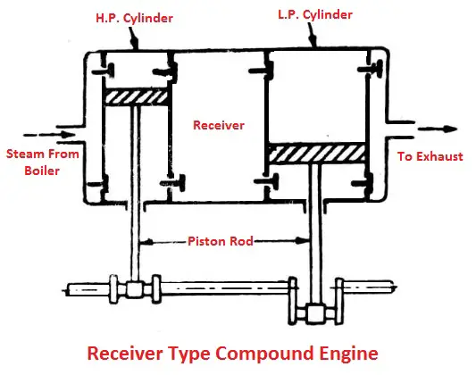
In a receiver type compound engine, the steam from the boiler is admitted to one side of the high-pressure cylinder. Since the two cranks are set at 90°, therefore the two cylinders are out of phase.
As a result, steam cannot pass directly from high-pressure cylinders to low-pressure cylinders.
It is therefore essential to introduce an intermediate vessel known as receiver between the high-pressure cylinder and low-pressure cylinder as shown in the figure. Steam from the high-pressure cylinder enters the receiver, from that it enters the low-pressure cylinder.
The figure shows the graph of turning moment versus crank angle of a receiver type compound engine. As the cranks are 90°apart, the two cycles are out of phase by 90°. The resulting turning moment diagram is also shown in the figure.
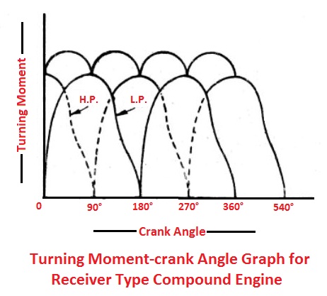
It will be noted that keeping the crank at 90 ° significantly reduces the variation of the turning moment, therefore a lighter flywheel is required. This is the main advantage of receiver type compound engines.
Advantages of Compounding
Following are the advantages of compounding the expansion of steam in two or more cylinders:
- There is a considerable economy in steam for high-pressure operations.
- A corresponding decrease in condensation temperature is limit per cylinder is minimized.
- The ratio of expansion is reduced, thus reducing the lens of stroke.
- Due to the pressure difference in these parts, the rear leakage of the valve and piston is minimized.
- The steam can be reheated after expansion and before entering the next.
- The mechanical balance can be made nearer and therefore high speeds are possible.
- In case of a breakdown, the engine can be adjusted to continue working at low load.
- The more uniform turning moment is exerted on the crankshaft, by spacing the cranks at 90° in the case of two-cylinder engines or at 120° in triple expansion engines. Thus a lighter flywheel is required.
- The forces in the working parts are reduced, as the forces are distributed over more parts.
- For the same power and economy, the cost of the engine is less than that of an ordinary steam engine.
Note:
Woolf type and Receiver type compound engines are cross-compound engines. In the cross-compound engine, the cylinders are provided side by side and each cylinder has a separate piston, which joins the rod and crank.
That’s it, thanks for reading. If you have any questions about “Compound Steam Engine” ask in the comments below. If you found this post helpful share with your friends.
Read Next:
- Engine: Types of Engines in Automobile
- Steam Engine: The Efficiency of Steam Engine
- Different Types of Boiler Draught with Advantages & Disadvantages
External Links and References:
- Compound steam engine: Wikipedia
- Compound steam-engine: Google patent
- Free patent online