In this article, you’ll learn what is a lubrication system and different parts of lubrication system with images and PDF.
Lubrication is essentially required in motor vehicle maintenance. To supply lubrication oil between the moving parts is simply termed as lubrication. lubrication of all moving parts (Other than nylon, rubber bushed or pre-lubricated components) is essential to reduce friction, wear and to prevent seizure.
Read More about Lubrication System:
Parts of Lubrication System
Following are the 8 different parts of lubrication system:
- Oil sump
- Oil pump
- Gear pump
- Rotor pump
- Plunger pump
- Vane pump
- Oil filter
- By-pass system
- Full flow system
- Oil strainer
- Oil cooler
- Oil level indicator
- Oil pressure gauge
- Pressure expansion type
- Electric-typeBalancing coil type
- Bimetal-thermostat type
- Oil pressure Indicating light
Read also: Lubrication System in Automobile: Method, Purpose & Application
Oil Sump
The oil sump is the lowest part of the crank chamber. It provides a covering for the crankshaft and contains oil in it. In wet sump lubricating system, the oil is taken out from the sump and after lubricating different parts, it drops in the sump.
The oil sump is also known as the oil pan. It usually made of steel pressings. Sometimes it is produced of aluminium or cast iron. It contains a drain plug at its lowest part to drain out the oil. In some cases, it contains oil strainer a barrel for dipstick and a connection for oil line. In a dry-sump lubricating system, the oil is contained in a separate oil tank.
Oil Pump
The oil pump is typically placed inside the crankcase below the oil level. The function of the oil pump is to supply oil under pressure to the varies engine parts to be lubricated. The different types of oil pumps used for engine lubrication are as follows,
- Gear pump
- Rotor pump
- Plunger pump
- Vane pump
1. Gear Pump
It consists of two meshed spur gears and closed in a housing. There is very little clearance between the teeth and housing of the gear. A gear is attached to a shaft that is driven from the engine camshaft or crankshaft through the appropriate gear.
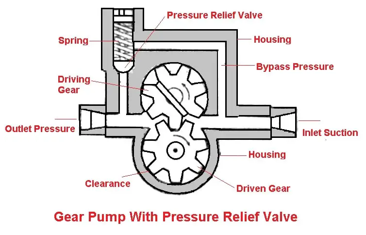
The other gear free to revolve on its own bearing. When the pump is in action, the oil-driven between the gear teeth from the inlet side. Carried around between the gears and pump housing, and forced out the outlet side. The pressure and volume of oil supplied by the pump depends on the speed of the gear.
This type of gear pump is almost generally employed in automotive engines due to its simplicity in construction. It can transfer oil at a pressure of about 2-4 kg/. A pressure relief valve is also provided in many oil pumps to relieve the excessive pressure due to high engine speeds or clogged oil lines.
2. Rotor Pump
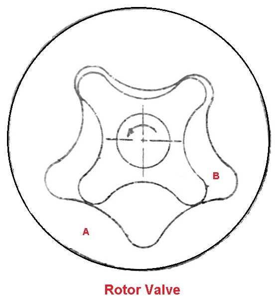
It consists of an inner and outer rotor within the pump body in place of gears, that is, two gears mesh internally. The external gear has the number of teeth one more than on the internal gear. The oil is displaced from the inlet to the outlet side just like the gear pump.
3. Plunger Pump
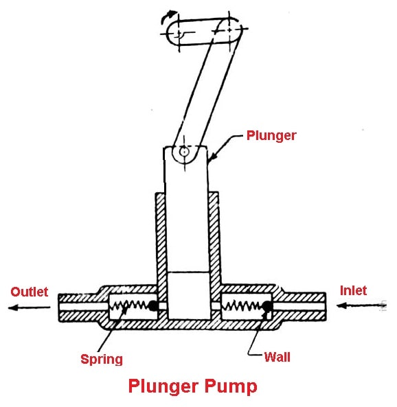
It consists of the plunger which reciprocates in the pump body while moving up, the plunger sucks oil from the inlet and while moving down it forces out the oil from the outlet. This type of sump is used to deliver oil under low pressure to the troughs of splash systems.
Read also: List of Car Engine Parts Its Function with (Pictures)
4. Vane Pump
It contains the cylindrical casing with outlet and inlet and drum. The drum is mounted eccentrically in the casing and contains two vanes with spring. With the drum rotates, the vanes wipe the oil from the inlet to the outlet side.
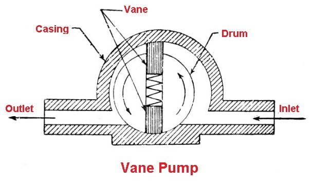
Because the drum is mounted eccentrically, the volume between the drum and casing constantly decreases and oil pressure increases at the outlet.
Oil Filter
The oil filter is used in the engine lubricating system of most of the motor vehicles to filter out the dirt or grit particle from the oil.
The oil filter systems are of the two types:
- By-pass system
- Full flow system
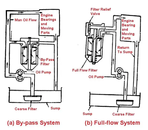
1. By-pass system
In the by-pass system, the whole of the oil does not pass through the filter at the same time, but some of the oil without being filtered goes to the bearings. The remaining oil passes through the filter and then to the bearing. When the engine is run continuously for a long period of time, the entire oil is filtered out.
2. Full flow system
In full flow system, the whole passes first through the filter and then goes to the bearing. If the filter is stopped for some reason, the system completely fails and the bearings will starve.
The different types of oil filters used in automotive engines. Are as follows:
- Cartridge type
- Edge type
- Centrifugal type
1. Cartridge type oil filter
It contains a filtering element placed in a metallic casing. The casing has an inlet and outlet oil pump enters casing through the filtering element, which takes up all the impurities.
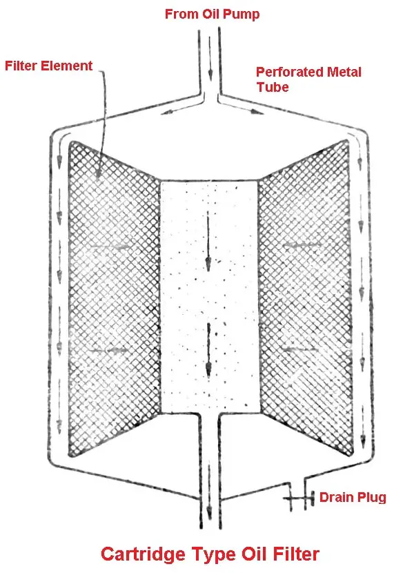
The filtered oil then comes out from the casing and goes to the oil gallery. The filtering element may be cleaned when clogged. If it is not in condition to be cleaned properly it should be replaced.
Read also:What are the 18 Different Properties of Lubricants [Lubricating Oil]
2. Edge type oil filter
It contains a number of the disc in the casing through which the oil passes. The alternate disc is mounted over a central spindle and the disc, between these, are fixed to a separate square rod. The clearance between the two discs in is only a few thousand of a centimetre.
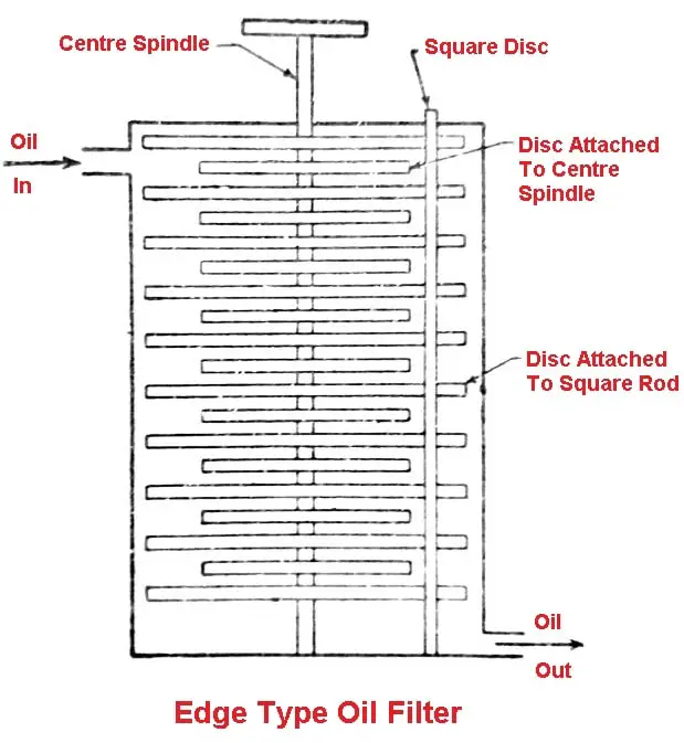
When the oil flows through this small clearance, it leaves impurities on the disc peripheries by operating the central spindle periodically the impurities so collected on the discs are removed.
3. Centrifugal type oil filter
Fig shows a centrifugal type oil filter. It contains a stationary casing, rotor casing, central spindle and tubes with jets. The impure oil enters the hollow central spindle and through whole around its periphery, the oil goes to the rotor casing.
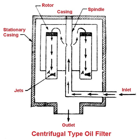
From the rotor causing the oil goes in the tubes, at the ends of which jets are attached. The oil passes through these jets under pressure, the reaction of which provides the motion to the rotor casing so that it begins to rotate.
The oil from the jets impinges on the walls of the stationary casing under heavy pressure, where the impurities are retained and the clean oil falls below, which is taken for use. The filter walls are cleaned periodically.
Read also: Four Different Types of Gearbox That Are Used In Modern Vehicles
Oil Strainer
Oil strainer is simply a wire mesh screen. It is attached to the inlet of the oil pump so that the oil going in the oil pump is free from impurities. The strainer retains the dirt or grit of the oil. Usually, a floating strainer installed which is hinged to the oil pump inlet.
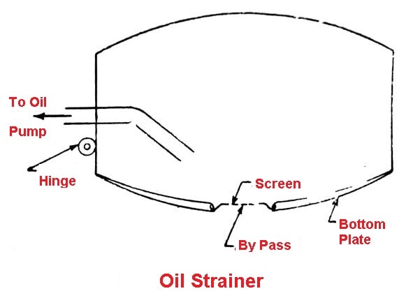
It is so adjusted that it floats at the oil surface and the impurities remain at the bottom of the crankcase. By doing so only a small amount of impurities goes to the strainer screen and hence it has less chances of being clogged. A by-pass is also kept in the strainer to allow the oil to pass when the screen is completely clogged.
Oil Cooler
The purpose of an oil cooler is to cool the lubricating oil in the heavy-duty engine where the oil temperatures become quite high. Because the viscosity of the oil decreases with the temperature rise and also the oil film may break at high temperatures, the oil must be kept cold in the lubricating system.
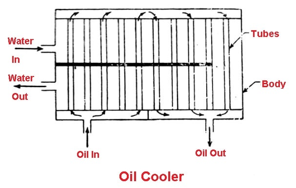
An oil cooler is just like a simple heat exchanger. The oil can be cooled with cold water from the radiator or air stream. Water type oil coolers are more commonly used in lubricating system because then act as reversible coolers.
At the time of starting when the water is hotter than the oil, the oil is heated to provide complete circulation in the system. At higher temperatures, when the oil becomes hotter than water, the water cools the oil.
A water type oil cooler, as shown in fig, simply consists of tubes in which oil circulates. The water circulates outside the tubes in the casing of the cooler. The heat of the oil carried away by the circulating water.
Oil Level Indicator
The level of the oil in the crankcase is checked by a dipstick. It is a long stick with a handle at one end for holding. It is graduated with marks full, half and empty. To check the oil level, the stick is dipped into the crankcase, and taken out.
The oil sticks on the stick which shows the oil level in the crankcase. The oil should fall below a critical mark. Before starting a vehicle particularly for a long journey. The oil level must be checked.
Oil Pressure Gauge
An oil pressure gauge is mounted on the instrument panel of all cars equipped with a pressure lubricating system to tell the driver what the oil pressure is in the engine. The oil pressure gauges are of the following types:
- Pressure expansion type
- Electric-type
- Balancing coil type
- Bimetal-thermostat type
1. Pressure Expansion Type Oil Pressure Gauge
Fig shows pressure expansion type oil pressure gauge. It contains hollow bourdon (curved) tube, that is fastened at one end and free at the other.
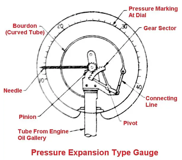
The oil pressure is applied to the curved tube through an oil line from the engine which causes the tube to straightened out. This movement is transmitted to a needle by linkage and gears from the end of the tube. The needle moves across the face of the dial indicating the oil pressure.
2. Balancing Coil Type Oil Pressure Gauge
It consists of two separate units/the engine and the indicating a unit. The engine unit consists of a moving contact that moves over a resistance according to the varying oil pressure against a diaphragm.
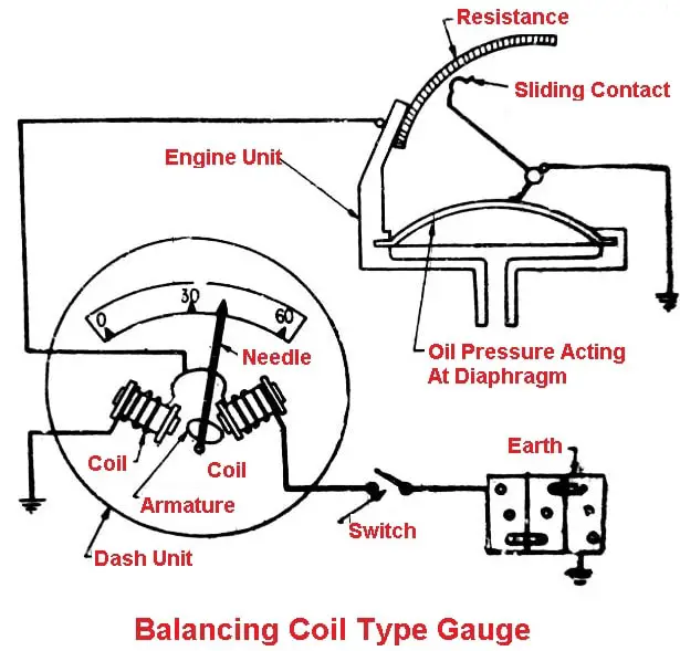
As the pressure increases, the diaphragm moves inward by which the contact moves along the resistance so that more resistance is placed in the circuit between the engine and indicating unit. This reduces the amount of current flowing in the circuit.
The indicating unit consists of two coils that balance the movement of the pointer on a scale, in a manner similar to the electrically operated fuel gauge.
3. Bimetal-Thermostat Type Oil Pressure Gauge
The metal thermostat type oil pressure indicator is similar to the bimetal thermostat furl gauge. It consists of an engine unit and a dash unit. The oil pressure on a diaphragm distorts the engine unit thermostat blade, and this distortion produces a similar distortion in the dash unit thermostat blade, causing the oil pressure to indicate on the dial.
Oil Pressure Indicating Light
In many motor vehicles, the engine oil pressure is indicated by a warning light. The light comes when the ignition switch is turned on and the oil pressure is low. The circuit user four-stage diaphragm switch which operates a warning a lamp according to the oil pressure required for different engine feeds.
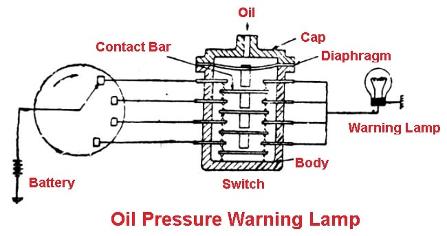
Fig shows an oil pressure warning lamp with a four-stage diaphragm operated switch. When the oil exerts pressure on the diaphragm the projection attached to it presses the uppermost contact bar, breaking the contact between the two projection further movement of the diaphragm deflects the second bar, and so on up to the fourth stage.
Each of these four stages is brought into a circuit with the warning lamp by a selector switch operated in conjunction with the speed-o-meter. In this way, the warning lights up only when the oil pressure falls below the value corresponding to the minimum engine speed.
That’s it, thanks for reading. If you have any questions about “Parts of Lubrication System” you can ask in the comments.
Want free PDFs? Then subscribe to our newsletter.
Download PDF file of this article:
Read Next:
we appreciate the knowledge shared to the people
Thank you.
Can you send me the pdf on my email please
I have sent the PDF file to your inbox.
Very good
Thanks for reading.