In this article, you will learn what is cylinder head? Its parts, functions, uses, and types of cylinder head are explained in detail with diagrams.
Download the PDF file at the end of the article.
Let’s start with what is a cylinder head.
What is Cylinder Head?
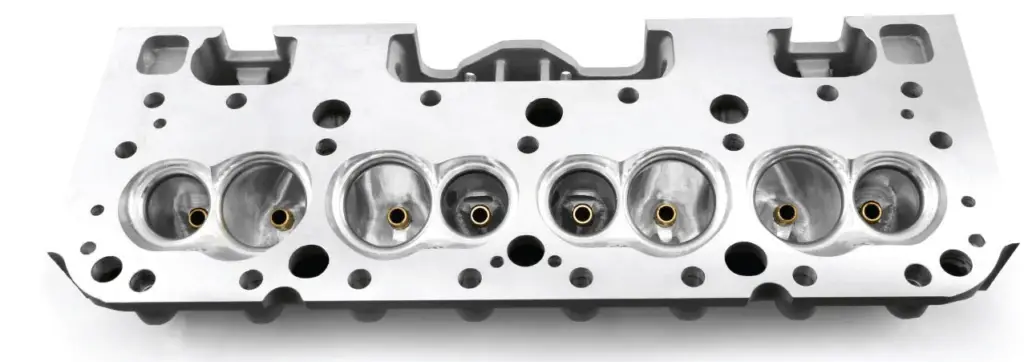
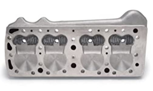
In an engine, the top of the cylinder is closed with a separate cast piece called the cylinder head. The cylinder head is bolted to the upper part of the cylinder block. This joint is covered by a head gasket. It consists of a combustion chamber, spark plugs, and sometimes valves (in the I and F-heads).
In most engines, the cylinder head includes passages that deliver air and fuel to the cylinders, and which allow exhaust gas to exit. The cylinder head is usually made of gray iron or aluminum alloy. Aluminum has the advantages of being lightweight and having high thermal conductivity.
Now, we will discuss the construction of the cylinder head.
Construction of Cylinder Head
It is cast separated from the cylinder block to eliminate it for cleaning carbon and grinding valve. To maintain compression within the cylinder, a flat piece of gasket is arranged between the cylinder head and the cylinder block.
In some cases, such as racing car engines, a separate head is not used. However, a single piece of the cylinder block and the head is difficult and costlier to make, and internal parts of the engine are not as accessible.
Depending on the valve layout, the cylinder head may have camshafts, rockers, and valves. Waterways are provided to accommodate valve and plug seating. From the mechanical point of view, the design details of a detachable cylinder head are perhaps the most difficult.
The following points should be kept in mind while making detachable heads:
- The bore of the cylinder or linear should not be distorted by the pull of the holding down studs.
- The circulation of coolant in the cylinder head should be taken as far as possible to the top end.
- To ensure a sound gas-tight joint, the holding studs must be distributed as uniformly as possible around the circumference of each cylinder.
Now, we will define every component that is found in the cylinder head.
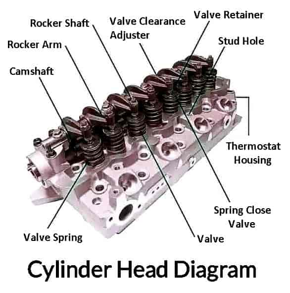
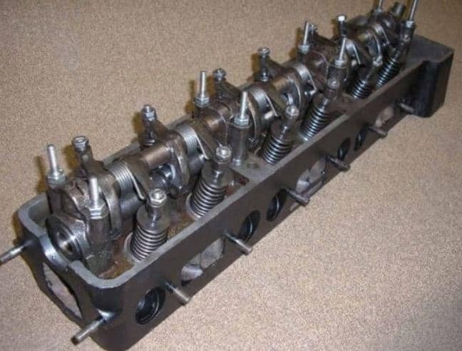
Parts of Cylinder Head
The cylinder head has several holes that connect the cylinder block to the cylinder head. Some of the holes are designed to accommodate water jackets for proper water circulation, which provides cooling and lubrication.
There are also some critical engine components in the cylinder head, including the inlet valve, exhaust valve, valve guides, injectors, spark plugs, etc. The combustion chamber in the SI engine is also located in the cylinder head. Additionally, there is an assembly for a heater plug and cylinder head injection.
There is a thermostat valve installed at the elbow of the radiator’s outlet for water circulation. A combustion chamber is a part of the cylinder head itself. In this, petrol or diesel is burned through a variety of intake and outlet manifold valves. Besides, it has holes for supplying oil to the cylinder at each stage.
Following are the parts of the cylinder head:
- Head gasket
- Intake and exhaust ports
- Head valves
- Head combustion chamber
- Spark plugs
- Fuel injectors
- Head camshaft
- Additional cylinder head parts
#1 Head Gasket
These are located between the cylinder head and the engine block. A head gasket is bolted on top of the engine housing. These gaskets act as a seal between the cylinder head and the engine block. This prevents the oil and engine coolant from leaking or mixing.
#2 Intake and Exhaust Ports
The intake and exhaust ports are part of the cylinder head. The intake port is meant to circulate air through a channel into the cylinder head and combustion chamber.
After the combustion process, the gases are removed from the combustion chamber by the exhaust port. This avoids the build-up of internal pressure, which can result in an explosion.
#3 Head Valves
An engine has valves to close and open, the purpose of which is to stop or prevent the entry of air and fuel into the combustion chamber. In an internal combustion engine, each cylinder has two valves – the intake valve is usually larger and the exhaust valve is smaller.
#4 Head Combustion Chamber
The head combustion chamber is called the core of the engine. In which the air-fuel mixture burns to generate the power to move the vehicle. Combustion chambers are available in various shapes and sizes. Well, it depends on the engine that you have and the application of the vehicle.
#5 Spark Plugs
The spark plug provides power to the combustion chamber to ignite the air/fuel mixture. Plugs are mounted on the cylinder heads, their tips leading directly to the combustion chamber. They are usually threaded to ensure an airtight seal.
#6 Fuel Injectors
You will also find fuel injectors on the cylinder head cover. In a diesel engine, injectors push the fuel into the combustion chamber by an injection pump.
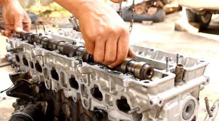
#7 Head Camshaft
The cylinder head also includes the camshaft. In this, the camshaft operates to open and close the valves. The crankshaft is one of the engine block components and uses a belt to drive the cylinder head camshaft.
#8 Additional Cylinder Head Parts
The cylinder head also has ports for the purpose of lubrication to cool the engine. Cylinder head port designs vary, as the head designs do. Basically, the purpose of every type of construction is to make the part as efficient as possible.
To understand where these parts are located, take a look at the cylinder head diagram below.
Function of Cylinder Head
The cylinder head plays an important role in a motor vehicle. The structure of the cylinder head is complex and consists of many ports. One of these ports is designed to work, and their common roles explain the value of this engine part.
It provides the mounting for various components such as inlet and outlet exhaust valves and ducts, spark plugs, fuel injectors, and camshafts. In addition, it gives way to coolant, oil, and combustion gases.
The cylinder block absorbs the heat produced by the engine and, therefore, generates cooling to prevent engine failure. It seals the combustion chamber and serves as the engine’s mechanical control powerhouse. It also takes away the compression resulting from the combustion pressure.
Read Also: How Does A Drum Brake Work?
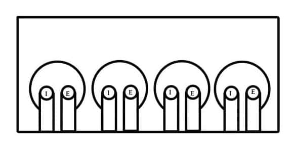
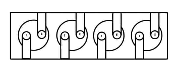
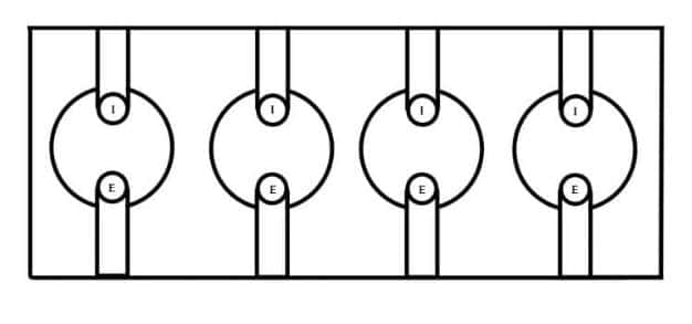
Four Designs of Cylinder Head
Figures show four designs of cylinder heads and the location of valves.
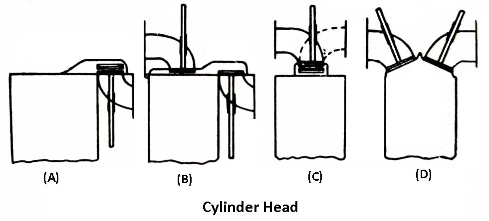
- At (a) is the popular side valve construction with all valves in line, the detachable head being of turbulence type. The piston closely approaches the flat position of the cylinder head.
- At (b) is shown the reverse valve construction of the cylinder head which gives good volumetric efficiency, as a large diameter inlet valve may be used, and the valve port gives direct access to the bore.
- In (c) is shown a cylinder head with vertical valves in a single line permitting the simple push rod and rocker gear.
- At (d) is an ideal hemispherical head which is used in many high-performance designs. In this design, the flame travel is short and high compression ratio can be readily provided by a domed piston crown.
Types of Cylinder Head
The cylinder head has been divided into several categories. It also depends on how the ports and valves are configured.
- Loop flow cylinder head
- Offset cross flow cylinder head
- In-line cross flow cylinder head
- Flat head cylinder head
- Overhead valve cylinder head
- Overhead camshaft cylinder head
- Water cooled engine
- Air cooled engine
We’ll now examine each of these cylinder heads types individually.
#1 Loop Flow Cylinder Head
The intake and exhaust ports on a loop flow cylinder head are located on the same side of the engine. In the cylinder head, the gases are introduced, and as they leave, they change direction.
In a loop flow engine, the starting inlet charge and the exhaust gas exiting the engine swirl in the same direction, which helps preheat the intake air. But when inlet and exhaust ports are lined up, there isn’t as much room on one side of the head, which results in a smaller port area than with a crossflow head.
#2 Offset Closet Flow Cylinder Head
When the intake and exhaust ports are on opposite sides, the cylinder head is said to be crossflow. In this type, gases are introduced to flow across the head. This type of cylinder head design is the opposite of the loop flow type, which has the ports on the same side.
They can also be operated by overhead camshafts, or by a valve train, which contains the camshafts in the cylinder block, and the valves are actuated by pushrods and rockers. Compared to the loop flow type cylinder head, the cross-flow type offers better performance and efficiency.
#3 In-line Cross Flow Cylinder Head
Both the offset cross-flow type and the inline cross-flow type of cylinder head have similar characteristics. There is a major difference here because the valves are arranged transversely and inclined.
However, the inlet and exhaust ports are placed across from one another, on different sides of the cylinder head. This configuration is superior in terms of performance and efficiency. However, because manufacturing would be expensive, it would not be practical.
The cylinder heads come in two varieties depending on the amount of cooling needed:
#1 Water-Cooled Engine
In the head of the water cooling engine, a number of water jackets are used to circulate the water. The water-cooled engine system is pressurized and sealed. The pressurized system used raises the water’s boiling point (above 110 °C).
As a result, water can be used for a longer period of time because the rate of evaporation slows. Hot engine components like the cylinder head and cylinder block release their heat through the circulation of water.
When water circulates through the radiator, a cooling fan is used to keep it cool. A liquid- or water-cooled engine is one that uses liquid to cool its internal combustion (IC) engine.
Most modern motorcycles, automobiles, and other vehicles have liquid- or water-cooled motors.
#2 Air-Cooled Engine
Air-cooled engines utilize fins for maximum cooling. It is lightweight and made of an alloy of aluminum. During operation, air is circulated over the hot parts of the engine to cool them so that the engine temperature remains within the operating range.
Most of the heat produced is lost through the exhaust, but some is also lost through the air-cooled engine’s metal fins. In order to remove heat from the engine, these engines have some fins that extend outward.
Then, cool air is forced over the fins using a fan. An air-cooled engine directly dissipates the heat created into the atmosphere. In contrast, a closed-circuit coolant-carrying system is used in liquid or water-cooled engines.
The cylinder head is classified into three types based on how it performs:
#1 Flathead Cylinder Head
These types of cylinder heads consist of a single piece of cast iron metal without any mechanical parts. Apart from the simple design, the flathead engine cylinder head type had its drawbacks.
The valves are located on the sides of the engine block. This causes the intake gases to move at a 90° angle, leading to inefficient combustion and a low compression ratio. Due to its design flaws, the flathead cylinder is no longer seen as common.
These are easy to manufacture and require low cost, the head allows the coolant to flow effectively. It is lightweight, as well as allowing for a compact engine. It can be found in small engines such as those used in lawnmowers, small tractors, and agricultural vehicles.
#2 Overhead Valve Cylinder Head (OHV)
Overhead-valve cylinder heads are complex in construction and are also known for I-type cylinder heads. This includes the valve train parts, spark plugs, and the passageways for intake and exhaust gases.
Engines with OHV cylinder head types tend to perform better due to the location of the valves and intake passages. In this, the flow of intake gases is fast and smooth due to the better design of the paths.
The advantage of installing this type is that the exhaust ports are also more efficient, plus the head does not get hot when compared to the flathead type. It also brings the camshaft closer to the crankshaft.
#3 Overhead Camshaft Cylinder Head (OHC)
These types of cylinder heads allow for valve train parts, spark plugs, and intake and exhaust ports, with the head, also housing the camshaft. In this, the location of the camshafts in the cylinder head varies. This can be in the middle, in the middle of a row of valves, or at the top of the valve.
An OHC cylinder head is available in two configurations which are single and dual. In a single OHC cylinder head, there are intake and exhaust valves in a single camshaft. In a dual OHC cylinder head, there are two separate camshafts for the intake and exhaust valves.
Based on how the ports and valves are arranged, cylinder heads are categorized below.
Automobile engines are classified into four categories based on the arrangement of the inlet valve and exhaust valve. These arrangements include the “L,” “I,” “F,” and “T” heads.
Remembering the word “LIFT” will help you recall the four-valve arrangement, making this topic simple for you to understand.
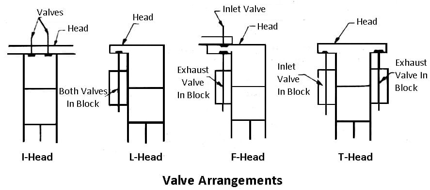
#1 F-Head Engine
I-head and L-head engines are combined to form the F-head engine. The exhaust valve of this type of engine is located in the cylinder block. Similarly, the inlet valve is typically located in the head. An individual camshaft is used to operate both valves.
#2 I-Head Engine
In an I-head design, both the inlet and exhaust valves are housed in the same cylinder head. All of the valves are operated by a single valve. Such types of engines are typically found in automobiles.
#3 L-Head Engine
In these engines, the inlet and exhaust valves are located side by side with one another and are operated by a single camshaft. The combustion chamber and cylinder combine to form an inverted L.
#4 T-Head Engine
The inlet valve and the exhaust valve are situated on either side of the cylinder in T-head engines. This system requires two camshafts to function. The inlet valve is operated by one camshaft, and the exhaust valve by the other.
Advantages of Cylinder and Head
The following are the advantages of the aluminum alloy cylinder and head:
- Higher heat conductivity which is about three times that of cast iron.
- Light in weight.
- Increased compression ratio without detonation due to the heat conductivity.
- Better cooling while the engine is running.
- Greater power output and low fuel consumption due to increased compression ratio and better cooling effect.
- The engine warms up more quickly and requires a smaller radiator.
Disadvantages
The following are the disadvantages of the aluminum alloy cylinder and head:
- The engine costs more due to quickly aluminum alloy.
- It is liable to be crusted out of shape by holding down studs due to the low modulus of elasticity.
- Due to higher thermal expansion, greater clearance is required between the piston and cylinder.
- Greater possibility of corrosion by cooling water.
- Sometimes, it is necessary to use cast iron valve seatings and spark plug inserts.
- Due to inter-metallic corrosion between steel studs and aluminum alloys, the head may stick to the cylinder blocks.
Applications of Cylinder Head
Following are the applications of cylinder head:
- The cylinder head is integrated with the cylinder block, in some cases commonly done in racing cars to achieve a gas-tight joint.
- The detachable head type has more benefits than integral construction.
- However, some heavy-duty engines requiring higher cooling rates such as those in racing cars may use copper alloys.
Conclusion
As you know now, it is a detachable metal that fits over the top of the cylinder block. Which is mainly used to close the combustion chamber of the engine from above. So now, I hope I’ve covered everything about the cylinder head parts, and their function.
If you still have any doubts or questions about the “cylinder head”, you can ask in the comments. If you like this article then please share it with your friends. Subscribe to our newsletter to get notified when we upload new posts.
Download PDF file of this article
You might like to read more on automobile engg in our blog:
- What is Propeller Shaft? It’s Diagram, Parts, Types, Functions, and More
- Flywheel: Parts, Working, Types, Applications, and More
- Connecting Rod: Parts, Types, Functions, Uses, and More [PDF]
External Resources:
Like it very informative thanks trying to find a school to get hands on
You’re welcome.
👍👍👍👍👍
Thanks.
Educative thank u….can I have the pdf
You’re welcome. The PDF file has been sent to your inbox.
Glad to be here with you people
Thanks for reading.
Thank you very much for providing useful information.
Glad you liked it!