In this article, you’ll learn about what are Intake and Exhaust Manifold, how they work? with its Construction, Working Principle, and More.
What is Engine Manifold?
Manifolds are separate sets of pipes connected to the cylinder head which provide the air-fuel mixture and the exhaust gases, these are known as manifolds. It is usually made of cast iron so that it is capable to resist the high temperature of the exhaust gases.
Read Also: The Complete List of Car Engine Parts: Its Function (With Pictures)
Types of Manifolds in Engine
Following are the two types of manifolds used in vehicles:
- Intake Manifold
- Exhaust Manifold
#1 Intake Manifold
The intake manifold is a cast iron or aluminum tube for carrying the air-fuel mixture from the carburetor to the engine intake port. Except where the superchargers or governors are used, the intake manifold is constructed so that, when the carburetor is attached to it, the mixture can reach each cylinder.
Constructional Details with Parts:
The carburetor is mounted on the intake manifold. The intake manifold has mounted a side of the cylinder block in L-head engines and on the side of the cylinder head in I-head engines. It is situated between the two cylinder banks on V-8 engines.
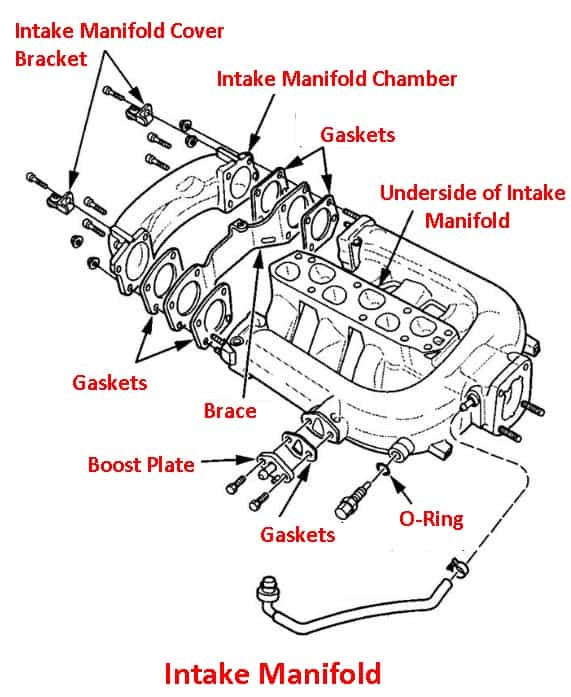
A good design of intake manifold consists of the path from the carburetor to the cylinders as short and short and smooth as possible so that the fuel will not condense and collect on the manifold walls. To minimize condensation and to assist in the vaporization of the gasoline in the mixture, the modern intake manifold is heated.
Read Also: Types of Shock Absorbers and its Working
Working Principle
The heat is usually supplied from the exhaust gases or cooling water, sometimes hot-spot are provided at points where the fuel strikes in the intake manifold. The heat supplied is controlled by a thermostat so that all the exhaust gases are deflected to heat the intake manifold when the engine is cold, and less heat is supplied as the engine warms up.
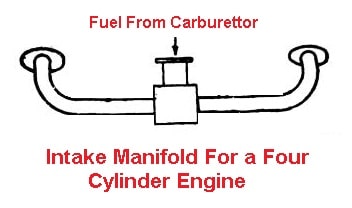
A single passage manifold directly connects the carburetor to the cylinder. In a four-cylinder engine, four passages each from a cylinder, submerge in one which connects the carburetor. For good distribution of the air-fuel mixture, it is desirable to have the distance of each of the cylinders from the carburetor approximately.
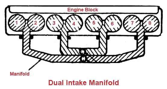
The dual carburetor is usually provided with dual intake manifolds having two branches, one for each barrel of the carburetor. Each of these braches feeds half of the engine cylinders, thereby preventing overlapping of the strokes in the manifold and thus improving the uniformity of distribution.
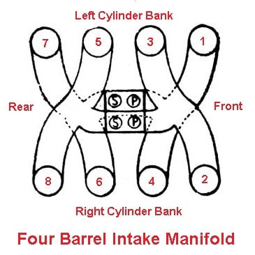
In a four-barrel intake manifold, the primary and secondary outlets for the same side of the carburetor lead the same cylinders 2, 3, 5, and 8, while the left-hand outlet leads to cylinders 1, 4, 6, and 7.
#2 Exhaust Manifold
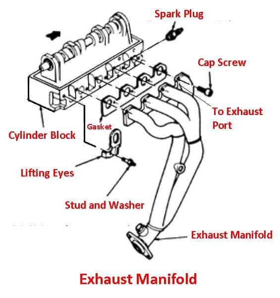
The exhaust manifold is a tube for removing the exhaust gases away from the engine cylinders. It collects exhaust gases from the exhaust ports of the various cylinders and conducts them to a central exhaust passage.
Constructional Details and Parts
The exhaust manifold is usually made of cast iron. It is bolted to the side of the cylinder block on L-head engines and to the side of the cylinder head on I-head engines. On V-8 engines, there are two exhaust manifolds, one for each bank of cylinders.
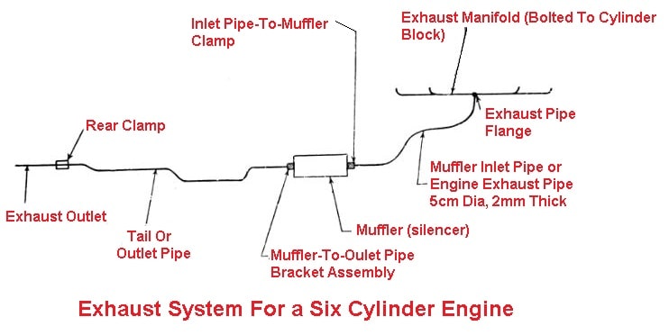
In some V-8 engines, each manifold is connected to a separate exhaust pipe, muffler, and tailpipe. On others, they are connected by a crossover pipe and exhaust through a common muffler and tailpipe. Fig shows an exhaust manifold for an eight-cylinder in-line passenger car engine.
Read Also: Types of Suspension Springs Used In Vehicles
Working Principle
The exhaust manifold is designed to avoid overlapping exhaust strokes, as far as possible, thus keeping the backpressure to a minimum. This is often done by dividing the exhaust manifold into two or more branches so that two cylinders will not exhaust into the same brach at the same time.
Large radius bends are provided in the design to eliminate any restriction to the flow. A heat tube may also be provided to furnish heat to the built-in automatic choke unit of the carburetor.
The center portion of the exhaust manifold is often connected to the intake manifold of an in-line engine through a heat trap and exhaust damper, except where the intake manifold is water heated.
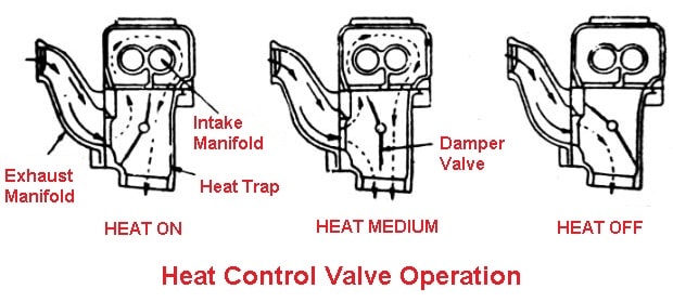
The damper is controlled thermostatically to deflect the exhaust gases around the intake manifold. When the engine is cold, all the exhaust gases pass around the intake manifold.
When the engine is warmed up, a part of the exhaust gases goes around it, and when the engine is fully warmed up none of the exhaust gases passes around the intake manifold, but goes directly to the exhaust pipe as shown in fig.
Read also:
That’s it, thanks for reading. If you have any questions about “types of manifolds” ask in the comments I’ll respond to you. If you like this article then please share it with your friends.
Subscribe to our newsletter to get notification of our new posts.
Download PDF of this article:
Read Next:
- Spark Plug: Types, Parts, Working Principle, Requirements
- Radiator: It’s Working Principle and Types of Radiator
- Types of Pistons [complete guide]
External Resources:
Great explanation! The diagrams really helped me visualize how intake and exhaust manifolds work together. I never realized they played such a crucial role in engine performance. Thanks for sharing the PDF as well!
Glad you found it helpful! The intake and exhaust manifolds are definitely key players in engine performance. Thanks for your feedback!
Great breakdown of the intake and exhaust manifold! I was confused about how they worked together, but your diagram and explanations really helped clarify things for me. Keep up the excellent work!
Thank you! Glad it helped clear things up for you. Always here to help! 😊