Slotter Machine
The slotter machine falls under the category of the reciprocating type of machine tool similar to a shaper to a shaper or a planner. It operates almost on the same principle as that of a shaper.
The major difference between a slotter machine and a shaper machine is that in a slotter the ram holding the tool reciprocates in the vertical axis. whereas in a shaper the ram holding the tool reciprocates in a horizontal axis. A vertical shaper and slotter machines are almost similar to each other as regards their construction, operation, and use.
The only difference being, in the case of a vertical shaper, the ram holding the tool may also reciprocate at an angle to the horizontal table in addition to the vertical stroke. The ram can be swivelled not more than 5° to the vertical.
The slotter machine is used for
- Cutting grooves, keyways and slots of various shapes.
- Used for making regular and irregular surfaces both internal and external.
- For handling large and awkward workpiece.
- For cutting internal or external gears and many other operations which cannot be easily machined in any other machine tool described before.
The slotter machine was developed by Brunel in the year 1800 much earlier than a shaper was invented.
Read also: Everything You Need To Understand About The Drilling Machine
Types of Slotter Machine
There are mainly two types of slotter machine.
- Puncher slotter.
- Precision slotter.
#1 Puncher Slotter
The puncher slotter machine is a heavy, rigid machine designed for removal of a large amount of metal from large forgings or castings. The length of stroke of a puncher slotter is sufficiently large. It may be as long as 1800 to 2000mm.

The puncher slotter ram is usually driven by a spiral pinion meshing with the rack teeth cut on the underside of the ram. The pinion is driven by a variable speed reversible electric motor similar to that of a planer. The feed is also controlled by electrical gears.
#2 Precision Slotter
The precision slotter machine is a lighter machine and is operated at high speeds. The machine is designed to take light cuts giving the accurate finish.
Using special jigs, the machine can handle a number of works on a production basis. The precision slotter machines are also used for general purpose work and are usually fitted with the Whitworth quick return mechanism.
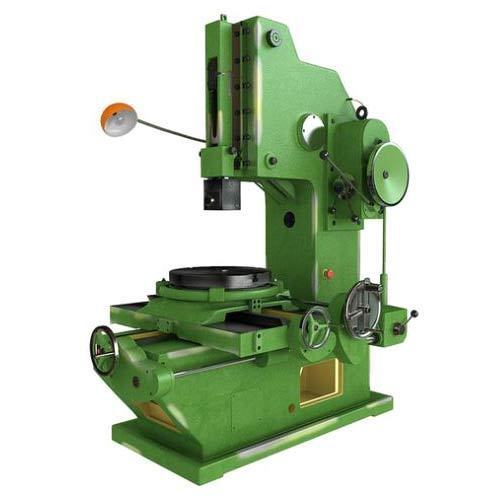
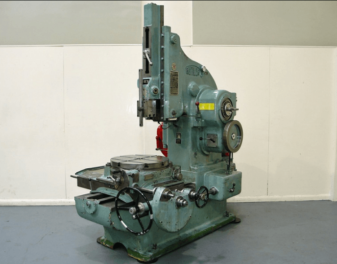
Parts of Slotter Machine
The different parts of a slotter machine are,
- Base.
- Column.
- Saddle.
- Crosslide.
- Rotating table.
- Ram and tool head assembly.
- Ram drive mechanism.
- Feed mechanism.

1. Base or Bed
- The base is rigidly built to take up all the cutting forces and the entire load of the machine.
- The top of the bed is accurately finished to provide guideways on which the saddle is mounted.
- The guideways are perpendicular to the column face.
2. Column
- The column is the vertical member which is cast integrally with the base and houses the driving mechanism of the ram and feeding mechanism.
- The front vertical face of the column is accurately finished to provide ways in which the ram reciprocates.
3. Saddle
- The saddle is mounted upon the guideways and may be moved toward or away from the column either power or manual control to supply longitudinal feed to the work.
- The top face of the saddle is accurately finished to provide guideways for the cross-slide. These guideways are perpendicular to the guideways on the base.
4. Cross-slide
- The cross-slide is mounted upon the guideways of the saddle and may be moved parallel to the face of the column.
- The movement of the slide may be controlled either by hand or power to supply crossfeed.
5. Rotary Table
- The rotary table is a circular table that is mounted on the top of the cross-slide.
- The table may be rotated by rotating a worm which meshes with a worm gear connected to the underside of the table.
- The rotation of the table may be affected either by hand or power. In some
- In some machines, the table is graduated in degrees that enable the table to be rotated for indexing or diving the periphery of a job in an equal number of parts.
- T-slots are cut on the top face of the table for holding the work by different clamping devices. The rotary table enables a circular or contoured surface to be generated on the workpiece.
6. Ram and Toolhead Assembly
- The ram is the reciprocating member of the machine mounted on the guideways of the column. It supports the tool at its bottom end on a tool head.
- A slot is cut on the body of the ram to change the position of the stroke.
- In some machines, a special type of tool holder is provided to relieve the tool during its return stroke.
Slotter Machine Mechanism
A slotter removes metal during the downward cutting stroke only whereas during the upward return stroke no metal is removed. The reduce the idle return time quick return mechanism is incorporated in the machine. The usual types of ram drive mechanisms are,
- Whitworth quick return mechanism.
- Variable speed reversible motor drive mechanism.
- Hydraulic drive mechanism.
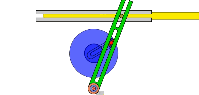
7.1 Whitworth Quick Return Mechanism
A simple Whitworth quick return mechanism as shown in Fig. The bull gear is mounted on a fixed hub at the rear end of the machine and it is rotated by a driving pinion from the motor. The driving plate is connected to the main shaft through the fixed hub. The main shaft is placed eccentrically with respect to the bull gear center.
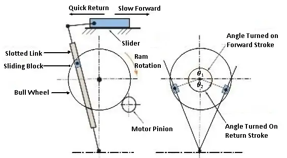
The bull gear holds the crankpin with a sliding block and slides in a driving plate. So that when the bull gear rotates, imparts rotary motion to the driving plate and shaft causing the disc to rotate at the end of the main shaft.
The disc is connected to the lower end of the connecting rod eccentrically by means of a pin in a radial T-slot on the face of the disc, which converts the rotary motion of the disc into the reciprocating motion of the ram connected to the top end of the connecting rod.
The Principle of a Quick Return Mechanism
The principle of the quick return mechanism can be explained simply by a line diagram. A and B are the fixed centers of the bull gear and the driving plate. The crack pin and the slide block rotate in a circular path at a constant speed in a driving plate about B. This causes the disc to rotate through the main shaft.
Pin 3 on the disc rotates in a circular path about the fixed point B. The length of the ram is equal to twice the narrow of eccentricity and it is equal to 2x3B (3B= throw of eccentricity). When the slide block is at C, the ram is at the maximum upward position of the stroke and when it is at D, the ram is at the maximum downward position.
If the bull gear rotates in an anticlockwise direction and the slide block rotates through an angle CAD, the ram performs a downward cutting stroke, whereas when the block rotates through an angle DAC the ram performs a return stroke.
As the block rotates at a constant speed the rotation of the slide block through an angle CAD during the cutting stroke takes longer time than the rotation through an angle DAC during the return stroke. Thus the quick return motion is obtained.
Slotter Size
The size of a slotter machine like that of a shaper is specified by the maximum length of stroke of the ram, expressed in mm. The size of a general-purpose or precision slotter usually ranges from 80 to 900mm.
To specify a slotter correctly the diameter of the table in mm. Amount of cross and longitudinal travel of the table expressed in mm. The number of speeds and feeds available, h.p. of the motor, floor space required, etc. should also be stated.
Slotter Machine Operations
- Machining cylindrical surface.
- Flat surface Machining.
- Machining irregular surface and cam machining.
- Machining slots, keyways, and grooves.
1. Flat Surfaces Machining
The external and internal flat surfaces may be generated on a workpiece easily in a slotter machine. The work to be machined is supported on parallel strips so that the tool will have clearance with the table when it is at the extreme downward position of the stroke.
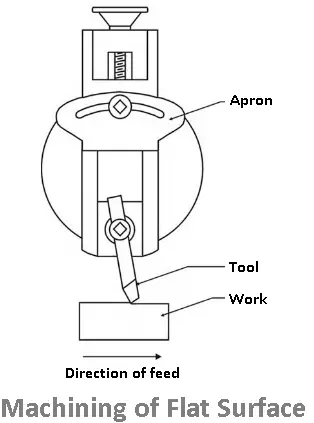
The work is then clamped properly on the table and the position and the length of the stroke is adjusted. A clearance of 20 to 25mm is left before the beginning of the cutting stroke, so that the feeding movement may take place during this idle part of the stroke.
The table is clamped to prevent any longitudinal or rotary travel and the cut is started from one end of the work. The crossfeed is supplied at the beginning of each cutting stroke and the work is completed by using a roughing and a finishing tool. While machining an internal surface, a hole is drilled into the workpiece through which the slotter tool may pass during the first cutting stroke.
A second surface parallel to the first machined surface can be completed without disturbing the setting by simply rotating the table through 180° and adjusting the position of the saddle. A surface perpendicular to the first machined surface may be completed by rotating the table by 90° and adjusting the position of the saddle and cross slide.
2. Machining Circular Surfaces
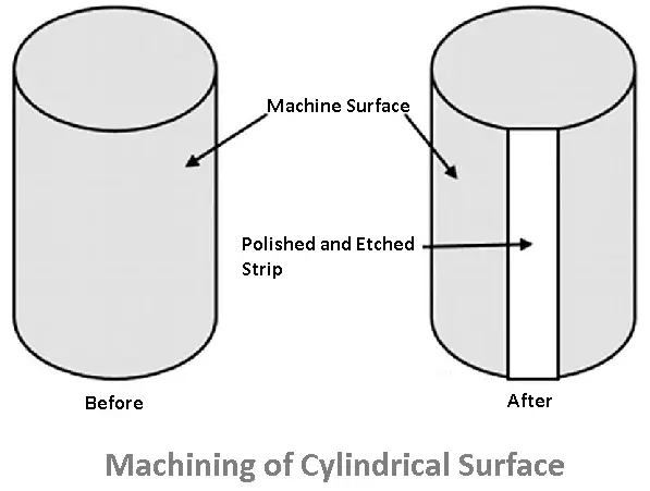
The external and internal surfaces of a cylinder can also be machined in a slotter machine. The work is placed centrally on the rotary table and packing pieces and clamps are used to hold the work securely on the table.
The tool is set radially on the work and necessary adjustments of the machine and the tool are made. The saddle is clamped in its position and the machine is started. While machining, the feeding is done by the rotary table feed screw which rotates the cable through a small arc at the beginning of each cutting stroke.
3. Machining Irregular Surfaces or Cams
The work is set on the table and necessary adjustments of the tool and the machine are made as detailed in other operations. By combining cross, longitudinal, and rotary feed movements of the table any contoured surface can be machined on a workpiece.
4. Machining Grooves or Keyways

Internal and external grooves are cut very conveniently by machine. A slotter is specially intended for cutting internal grooves which are difficult to produce in other machines.
External or internal gear teeth can also be machined in a slotter by cutting equally spaced grooves on the periphery of the work. The indexing or dividing of the periphery of the work is done by the graduations on the rotary table.
Advantages of Slotter Machine
The following are slot machine benefits:
- In comparison to other machine tools, the slotter machine is a lightweight machine.
- This machine does not have a very high cost.
- Low maintenance is necessary.
- A workpiece produced by these types of machines has a good surface finish.
Disadvantages
- The worker needs to know how to operate the machine, which is one of the Slotter Machine’s disadvantages.
- Another is that the machine’s construction is not straightforward.
Difference between shaper and slotter machine
- In shaper machines, the direction of the cutting stroke is horizontal with slower than the return stroke. But in slotter machines, the direction of the cutting stroke is vertical with slower than the return stroke.
- In the shaper, the Ram holding the tool reciprocates on a horizontal axis whereas, in the slotter, the ram holding the tool reciprocates on a vertical axis.
- A Shaper machine is used to produce horizontal, vertical, or inclined flat surfaces. Whereas in slotter machine is used for cutting keyways, grooves, and slots of various shapes, for making regular and irregular surfaces both external and internal, for cutting internal gears, and for handling large and awkward jobs.
Download Pdf of this article

Read also: Lathe machine and Types of Lathe
Hey if you like the article on “slotter machine” share it with your friends. If you have any question leave a comment.
Very insightful thanks for sharing
You’re welcome.
Wow, this is awesome. You covered almost everything about slotter machine. That’s for this awesome article
Thank you
Great article
Thanks for sharing this Information in slotting machine
Happy to help 🙂
Great artical
Thanks