In this article, you will learn what is micrometer and types of micrometer screw gauge. And its parts, measuring accuracy, how to read, and more with PDF
Micrometer Screw Gauge
The micrometer is an improvement over the measurement of the vernier caliper scale.
The accuracy of the vernier caliper remains 0.02 mm, but most of the engineering precision work demands greater accuracy with sensitivity for which an instrument having both these should be used.
The most familiar precision measuring instrument in the workshop is the micrometer.
Micrometer works on the principle of screw and nut. The longitudinal movement of the spindle during one rotation is equal to the pitch of the screw i.e., the distance moved by the nut along the screw is proportional to the number of revolutions made by the nut.
Therefore by controlling the number of revolutions and fractions of a revolution made by the nut, the distance it moves along the screw can be accurately predicted.
To apply the above principle to a measuring device, it requires:
- Precision screw.
- A means of cunting the whole revolution of the screw.
- A means of measuring the extent of the partial revolutions.
Any micrometer will show all these principles included. The screw thread is rotated by the thimble which indicates the partial revolution, the whole revolutions being counted on the barrel of the instrument.
Read also: Different Types of Vernier Calipers [Complete Guide]
Micrometer Reading
As we know that the screw thread is rotated by the thimble which indicates the one-sided revolution. and the whole revolution being counted on the barrel of the instrument.
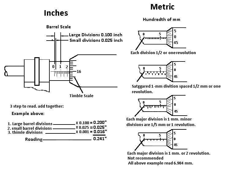
The screw has a lead of 0.5 mm and the thimble and barrel are graduated as shown in the figure below.
As the pitch of a single start screw of a standard metric micrometer is 0.5 mm and the barrel division is 0.5 mm apart, one revolution of the thimble will move a distance of one barrel division.
As a thimble has 50 divisions and one revolution of thimble equals 0.5 mm, then a movement of one thimble division is 0./50= 0.01 mm.
The micrometer reading equals:
- The largest visible ‘whole’ millimetre +
- The largest visible ‘half’ millimetre +
- The thimble division is coincident with the datum line.
For the given figure, the reading is:
9 whole millimetre = 9.00
a half-millimeter = 0.50
48 hundredths of mm (48 Χ 0.01) = 0.48 = 9.98 mm
Read Also: 12 Different Types of Fasteners [Their Uses & Examples]
Types of Micrometer Screw Gauge
The following are the four common types of micrometer screw gauges and 3 special-purpose types of micrometers.
Outside Micrometer
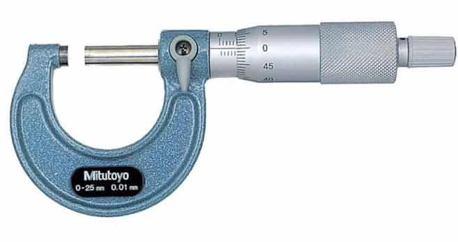
A micrometer or side micrometer is used to measure the dimensions of small components for greater accuracy. It provides direct reading and is made in various patterns to suit particular applications.
Below is the general arrangement of the outside micrometer and its various parts. Regardless of the type or size of an outside micrometer, they contain the basic parts like: Frame, Anvil and spindle, Ratchet driver, Thimble and Barrel, and Adjusting Nut.
Inside Micrometer
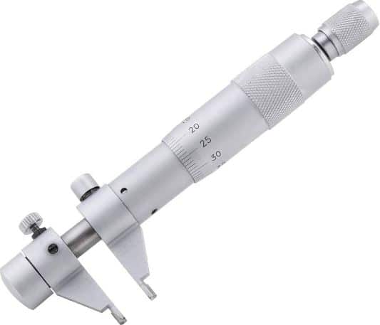
The figure below shows an inside micrometer. These types of micrometers, do not have a U-shape frame and spindle. The measuring tips are constituted by the jaws with contact surfaces which are hardened and ground to a radius.
One jaw is held stationary at the end, and the second one moves by the movement of the thimble. A locknut is provided to check the movement of the movable jaw. These are used for inspecting small internal dimensions. Its range is from 5 to 50 mm. It is not so widely used.
Micrometer Depth Gauge
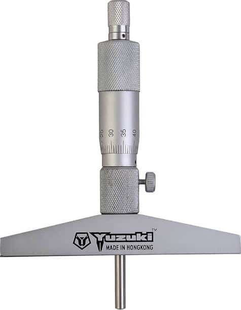
These types of micrometers are used for measuring the depth of holes. The micrometer depth gauge is used for measuring the depth of holes, slots, and recessed areas.
It has one shoulder which acts as the reference surface and is held firmly and perpendicular to the center line of the hole.
For a large range of measurements, extension rods can be used. The screw of the micrometer depth gauge has a range of 20mm or 25mm.
The length of the micrometer depth gauge varies from 0 to 225mm. The rod is inserted through the top of the micrometer. The rod is marked after every 10mm so that it can be clamped at any position.
Vernier Micrometer
To increase precision, outside micrometers can also be used using the vernier principle, allowing for measurements with a resolution of 0.001 mm. There are two sets of divisions on the barrel’s main scale.
The upper set, above the line, denotes half-millimeter increments, while the lower set, below the reference line, shows measurements in millimeters.
The thimble itself has a thimble scale with 50 equal segments. Every tiny division on the thimble is equal to 1/50th of the 0.5 mm smallest main scale division. The barrel has a vernier scale with 10 divisions, which is equivalent to 9 divisions on the thimble.
As a result, 9-10 of a thimble division is similar to one division on the vernier scale. One thimble division is 0.01 mm, so a vernier scale division is 0.009 mm.
Bench Micrometer
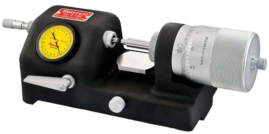
The bench micrometer principle makes use of a magnifying technique i.e., a gap of 0.01mm between the anvils is equivalent to a division width of the thimble of about 1mm.
Thus the actual distance is magnified approximately 100 times. The greater the diameter of the thimble the greater modification is possible.
Screw Thread Micrometer
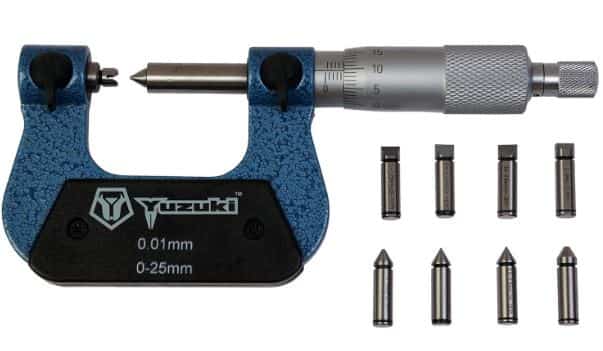
This type of micrometer is similar to the ordinary micrometer with the difference that it is equipped with a special anvil and spindle.
The anvil has an internal Vee which fits over the thread and is free to rotate. Thus the Vee can accommodate itself to any rake range of thread.
The spindle has a ground conical shape. When the conical spindle is brought into contact with the Vee of the anvil, the micrometer reads zero, depending upon the threads to be measured different sets of anvils are provided.
A thread micrometer is used for the measurement of the pitch diameter and the accuracy is very much dependent on the helix angle of the thread.
Screw thread micrometer as shown in fig and designed to measure the pitch diameter of screw threads to thousands of accuracy for varying diameters of work and each normally covers a range of threads per mm.
Vee – Anvil Micrometer

As their implies, have a tapered spindle and a V-shaped carbide-tipped anvil. They are designed for measuring odd-fluted taps, milling cutters, and reamers, as well as checking out of roundness to tenths of thousands accuracy.
In these types of micrometers, the angle of the Vee equals 60 degrees and the apex of the Vee coincides with the axis of the spindle.
The zero reading of the micrometer starts from a point where the two sides of Vee meet.
It is interesting to see that as the angle of Eve is 60° the micrometer will measure a distance of 1.5d for a round piece of diameter’ It is simple to obtain from reading.
Thickness Micrometer
It is not convenient to use the ordinary micrometer for measuring the thickness of the tube (cylinder) or sleeve because of the concavity of the internal surface.
These types of micrometers are used for measuring the thickness of cylinder walls. For this purpose, the anvil is provided with a spherical measuring surface of the frame cut away on the outside to permit the anvil to be introduced into tubes of diameter as small as 5.00mm in an alternative design shown in the figure.
The anvil is made of cylindrical form, its axis being perpendicular to the axis of the spindle. Micrometer for measuring the thickness of tubing no less than 12 mm inside diameter.
Digital Micrometer
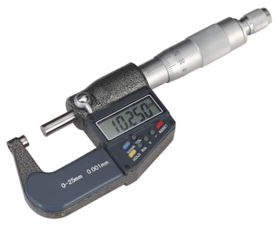
Even while mechanical measuring instruments such as vernier calipers and micrometers can measure with an accuracy of less than 0.001 mm, they are not adequate when more precision is needed. As a result, precision and user-friendliness have made digital and electronic instruments commonplace in industrial measurement.
The fundamental parts of a digital micrometer include the LCD, an ON/OFF ZERO key, spindle, barrel, locknut, thimble, and ratchet in addition to the frame.
A digital micrometer provides unparalleled precision and the convenience of digital readings, and they come in a range of sizes, typically ranging from 0-25 mm up to 75-100 mm.
Read Also: What is a Manometer?
Precautions In Using a Micrometer Screw Gauge
The following precautions must be adopted to obtain accurate readings.
- The micrometer should be cleaned of any dust and the spindle should move freely.
- The part of the dimension to the checked is held in the left and the micrometer in the right hand. The way to hold a micrometer is to place the small finger and adjoining finger in the U-shaped frame. The forefinger and thumb are placed near the thimble to rotate it and the middle finger supports the micrometer holding it firmly.
- Then the micrometer dimension is set larger than the size measured and the part is slid over the contact surfaces of the micrometer gently. Then the thimble is turned till the measuring tip touches the part and the final movement is provided by a ratchet so that uniform measuring pressure is applied.
- The micrometer is available in variations sizes and ranges and the corresponding micrometer should be chosen depending upon the dimension.
Care of the Micrometer Screw Gauge
The following care should be taken when a micrometer is being used.
- Never drop a micrometer, always place it down gently in a clean place.
- Never place tools or other materials on a micrometer.
- Don’t lay a micrometer in a steel ship or grind dust or handle with oily hands.
- Never attempt to use it on a moving work.
- Keep the micrometer clean and accurately adjusted.
Errors In Micrometer Screw Gauge
Some possible sources of errors which result in the incorrect functioning of the instrument are listed below:
- Lack of flatness of the anvils.
- lack of parallelism of the anvil at particular or all parts of the scale.
- The inaccurate setting of zero reading.
- Inaccurate reading following the zero position.
- Inaccurate reading is shown by the fractional divisions on the thimble.
Advantages of Micrometer Screw Gauge
- More accurate than rules.
- Greater readability than rules or vernier.
- No parallax error.
- Small, portable, and easy to handle.
- Relatively inexpensive.
- Retains accurately better than verniers.
- Has to wear an adjusting facility.
- End measurement.
Disadvantages Micrometer Screw Gauge
- Short measuring range
- Single-purpose instrument
- Limited wear area of the anvil and spindle tip.
- End measurements only.
Conclusion
So now, I hope I’ve covered everything about the “Slot Milling“. If you have any questions or doubts about this article, you can ask in the comments. If you liked this article, then please share it with your friends.
Want free PDFs direct to your inbox? Then subscribe to our newsletter.
Download PDF of this article

Read more in our blog:
- Types and Difference Between Unilateral & Bilateral Tolerance
- What is Sine Bar? And Its Working Principles & Application
- Different Types of Cutting Tools & Their Uses
FAQs
A tool used to measure the diameter of thin wires and the thickness of small sheets, such as plastic or glass, is called a micrometer screw gauge.
A micrometer screw gauge consists primarily of a frame, anvil, sleeve or barrel, locking nut, spindle, thimble, and ratchet stop.
Total Reading = Pitch Scale Reading + Circular Scale Reading x LC of the gauge.
LC represents the gauge’s least count. The zero of the pitch scale may differ from the zero of the circular scale.
The zero error occurs when an instrument does not read zero when the quantity to be measured is zero. No matter what value is being measured, this error is important since it may result in errors in all measurements made with that instrument.
This is the whole content about micrometer screw guage, I have liked it
Glad you liked it, Thank you so much 🙂
thanks. that is very useful for me.
You’re welcome