In this post, you learn about abrasive jet machining. Its working principle, parts, applications, advantages, and disadvantages.
What is Abrasive Jet Machining?
Abrasive jet machining is a process consisting of impinging high-speed streams of abrasive particles onto a work surface through a nozzle, causing erosion to occur on the surface as a result of high-speed particles.
Small pieces of material become loosened from repeated hits and are swept away by the jet, exposing the newly exposed surface to the jet.
The impact of the particles produces a sufficient concentration of force to assist with operations such as cutting. Work material is removed by the erosion of grits at speeds between 150 and 300 m/s. The abrasive grains are applied in a gas stream at a high velocity.
Read Also: What Are The Types of Welding Processes & Their Uses?
Working Principle of Abrasive Jet Machining
The fundamental principle of Abrasive jet machining involves using a high-speed stream of abrasive particles carried by a high-pressure gas or air on the work surface through a nozzle.
The metal is removed due to erosion caused by the high speed of abrasive particles impacting the work surface. With repeated impacts, small bits of material get loosened and a fresh surface is exposed to the jet.
This process is mainly employed for machining works that are otherwise difficult, such as thin sections of hard metals and alloys, cutting of material sensitive to heat damage, producing intricate holes, deburring, etching, polishing, etc.
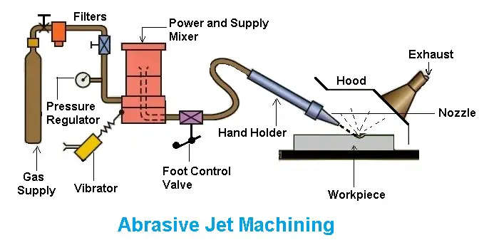
Parts of Abrasive Jet Machine
Following are the parts of abrasive jet machining:
- Gas supply
- Nozzle
- Abrasive
- Workpiece
- Pressure regulator
- Filters
- Foot control valve
- Holder
- Hood
#1 Gas Supply
The filtered gas, supplied under a pressure of 2 to 8 kgf/cm to the mixing chamber containing the abrasive powder and vibrating at 50 Hz entrains the abrasive particles and is then passed into a connecting hose.
This abrasive and gas mixture emerges from a small nozzle mounted on a fixture at a high velocity ranging from 150 to 300 m/min.
#2 Abrasive
The abrasive powder feed rate is controlled by the amplitude of vibration of the mixing chamber. The gas flow and pressure is controlled by a pressure regulator. To control the size and shape of the cut either the workpiece or the nozzle is moved by cams, pantographs, or other suitable mechanisms.
The abrasives generally used are silicon carbide, aluminum oxide, glass powder, or specially prepared sodium bicarbonate. The common particle sizes vary from 10 microns to 50 microns. Smaller sizes are used for good surface finish and precision work. While larger sizes are used for rapid removal rate.
In addition to the above abrasives, dolomite (calcium magnesium carbonate) of 200 grit size is found suitable for light cleaning and etching. Glass beads of diameter 0.30 to 0.60 mm are used for light polishing and deburring.
#3 Nozzle
Nozzles have a great degree of abrasion wear, they are made of hard materials such as tungsten carbide or synthetic sapphire to reduce the wear rate.
Nozzles made of tungsten carbide have an average life of 8 to 12 hours. While nozzles of sapphire last for about 300 hours of operation when used with 27-micron abrasive powder. The gases used are nitrogen, carbon dioxide, or clean air.
#4 Workpiece
The metal removal rate depends upon the diameter of the nozzle, the composition of the abrasive gas mixture, the hardness of abrasive particles and that of the work material, particle size, the velocity of the jet, and the distance of the workpiece from the jet. A typical material removal rate for abrasive jet machining is 16 mm/min in cutting glass.
Read also: Types of Unconventional Machining Process [Manufacturing]
Working of Abrasive Jet Machining
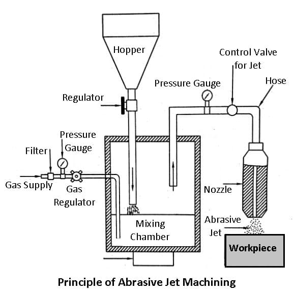
A typical set-up for abrasive jet machining is shown in the figure. The abrasive particles are held in a suitable holding device, like a tank, and fed into the mixing chamber. A regulator is incorporated in the line to control the flow of abrasive particles compressed air or high-pressure gas is supplied to the mixing chamber through a pipeline.
This pipeline carries a pressure gauge and a regulator to control the gas flow and its pressure. The mixing chamber, carrying the abrasive particles is vibrated and the amplitude of these vibrations controls the flow of abrasive particles.
These particles mix in the gas stream, travel further through a hose and finally pass through the nozzle at a considerably high speed. This outgoing high-speed stream of the mixture of gas and abrasive particles is known as an abrasive jet.
Accuracy
With close control of the various parameters, a dimensional tolerance of +0.05 mm can be obtained. On normal production work, the accuracy of +0.1 mm is easily held.
Design consideration for AJM
| Material removal is done with cutting speeds between 25 – 125 mm/min. |
| Dimensional tolerances are in the range of ± 2 to ± 5 µm. |
| Surface finish with Ra values varies from 0.3 to 2.3 µm. |
Applications
- The process finds application in cutting slots, thin sections, contouring, and drilling, for producing shallow crevices, deburring, and producing intricate shapes in hard and brittle materials.
- It is often used for cleaning and polishing plastic, nylon, and Teflon components, the frosting of the interior surface of the glass tubes, etching of markings on glass cylinders, etc.
- It is used for deburring, etching, and cleaning of brittle metals, alloys, and non-metallic materials.
- Polishing of plastic, Nyon can be done easily.
- Drilling can be done easily.
- The fragile material can be easily machined.
Advantages of Abrasive Jet Machining
- Ability to cut intricate hole shapes in materials of any hardness and brittleness.
- Ability to cut fragile and heat-sensitive materials without damage as no heat is generated due to the passing of gas or air.
- Normally inaccessible portions can be machined with fairly good accuracy.
- Low capital cost.
Disadvantage of Abrasive Jet Machining
The disadvantages of the process lie in the following:
- The material removal rate is slow and its application is therefore limited.
- Flaring can become large.
- The machining accuracy is poor and the nozzle wear rate is high.
- Additional cleaning of the work surface may occur as there is a possibility of sticking abrasive grains in softer materials.
- It is an expensive process.
That’s it, thanks for reading. If you have any doubts or questions about “abrasive jet machining” ask in the comments. If you found this article helpful share it with your friends.
Want free PDFs direct to your inbox? Then subscribe to our newsletter.
Read More:
- What is TIG & MIG Welding: Difference Between TIG and MIG welding
- What is Underwater Welding and types of Underwater welding?
- Different Types of Welding Positions Explained
Resources or External Links: