In this article, you learn what is ultrasonic machining. How does it work? Parts, Applications, Advantages, and Disadvantages of ultrasonic machining.
Download the free PDF file of this article at the end of it.
What is Ultrasonic Machining?
The term ultrasonic is used to describe a vibratory wave of the frequency, that is above the upper-frequency limit of the human ear, i.e. above 16 kHz.
The device for converting any type of energy into ultrasonic waves is the ultrasonic transducer.
This electrical energy is converted into mechanical vibrations. For this, the piezoelectric effect is used in the magnetostriction display exhibited by natural or synthetic crystals or some metals.
Magne-restriction means that the change in amplitude that occurs in ferromagnetic materials is subject to an alternating magnetic field.
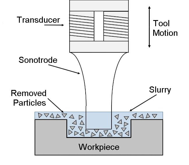
In ultrasonic machining, a tool vibrating longitudinally at 20 kHz to 30 kHz with an amplitude between 0.01 mm to 0.06 mm is pressed onto the work surface with a light force.
As the tool vibrates with a specific frequency, an abrasive slurry, usually a mixture of abrasive grains and water of fixed ratio (20% – 30%), flows under pressure through the tool-workpiece interface.
The impact force arising out of the vibration of the tool end and the flow of slurry through the work-tool interface causes thousands of microscopic grains to remove the work material by abrasion. The tool has the same shape as the cavity to be machined.
The method is employed to machine hard and brittle materials that are either electrically conducting or non-conducting. Analysis of the mechanism of material removal by the USM process indicates that it may sometimes be called Ultrasonic Grinding (USG).
Read Also: 16 Common Types of Welding Defects [Causes & Remedies]
Parts of Ultrasonic Machining
The following are the main parts of ultrasonic machining:
- Power supply
- Velocity transformer
- Abrasive slurry
- Tool
- Abrasive gun
- Eletroc-mechanical transducer
- Workpiece
#1 Power Supply
The term “power supply” refers to an electronic oscillator or high-frequency generator. It aims to convert a 50-60 HZ electrical supply to a high-frequency electrical supply ranging from 20-40 kHz with low vibration amplitudes up to microns.
#2 Velocity Transformer
Velocity transformer is another name for the horn’s design. Its goal is to focus and amplify the transducer’s vibration to a level of intensity that will drive the tool and complete the cutting operation.
It is made of tough, non-magnetic steel that is simple to machine and has good fatigue strength, such as K-Monel, Metal Bronze, and Mild Steel.
#3 Abrasive Slurry
At the site of machining, abrasives have to be applied and removed together with machined material from workpieces and tools, so a slurry is carried between them. The tool is placed against the workpiece to apply a light pressure that is high enough to ensure workplace fracture and low enough to avoid crushing abrasives.
The fracture strength of abrasives is greater than that of the workpiece. Abrasives must be supplied initially. As a result, they are applied to the machining site in a slurry, which is typically a water medium.
#4 Tool
A body known as the tool performs the hammering action. It is made of a sufficiently ductile material to prevent brittle fracture on its own. To increase material removal, we must increase the hammering rate to ultrasonic frequencies, so tool wear should be sufficient, and it should also be fatigue-resistant.
In that case, the tool material will be subject to dynamic loading. So, it ought to be resistant to fatigue. This hammering is proportional to the rate of machining.
#5 Abrasive Gun
The pump is also known as an abrasive gun and is a component of the ultrasonic machining process. It is used to supply the abrasive slurry at the interface between the tool and the workpiece under a specific amount of pressure.
#6 Eletroc-mechanical Transducer
A transducer’s primary job is to convert electrical energy into mechanical vibration. A transducer receives a high-frequency electrical signal and converts it into a high-frequency vibration with a low amplitude.
Ultrasonic machining employs two different types of transducers, which are described below:
- Piezoelectric transducer
- Magneto-restrictive transducer
Piezoelectric Transducer
This transducer produces a small electric current when it is compressed. It will enlarge when an electric current is passed through it. When the current is turned off, the crystal returns to its original dimensions. These types of transducers can handle up to 900 Watts of power.
Magneto-restrictive Transducer
These types of transducers also change shape when exposed to a magnetic field. These transducers have an efficiency of about 20–30% and are made of nickel and nickel alloy. These transducers can produce up to 2000 Watts. The largest length variation is about 25 microns.
#7 Workpiece
Engineering ceramics and other brittle non-conductive materials can be machined using ultrasonic machining. The workpiece is not thermally harmed, and no residual stress is applied to the workpiece. From this process, the workpiece can have intricate 3-D shapes.
Read Also: Different Types of Metals and Their Properties & Uses [Full Guide]
Working Principle of Ultrasonic Machining
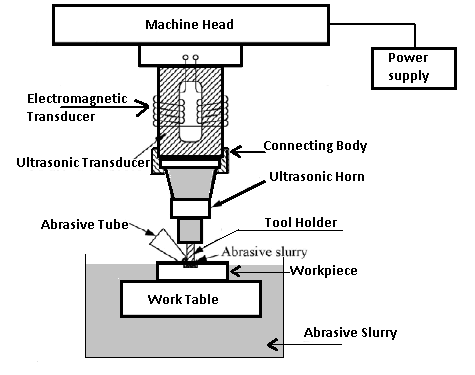
The figure shows the Ultrasonic machining operation. The electronic oscillator and amplifier, also known as the generator, converts the available electrical energy of low frequency to high-frequency power of the order of 20 kHz which is supplied to the transducer.
The transducer operates by magnetron striction. The high-frequency power supply activates the stack of the magnetostrictive material, which produces longitudinal vibratory motion of the tool. The amplitude of this vibration is inadequate for cutting purposes.
This is, therefore, transmitted to the penetrating tool through a mechanical focusing device which provides an intense vibration of the desired amplitude at the tool end.
The mechanical focusing device is sometimes called a velocity transformer. This is a tapered shank or called a ‘horn.’ Its upper end is clamped or brazed to the lower face of the magnetostrictive material. Its lower end is provided with means for securing the tool.
All these parts, including the tool made of low-carbon or stainless steel to the shape of the desired cavity, act as one elastic body that transmits the vibrations to the tip of the tool.
Read Also: Types of Unconventional Machining Process
Commonly Used Abrasives
Aluminum oxide (alumina), boron carbide, silicon carbide, and diamond dust are commonly used as abrasives. Boron is the most expensive abrasive material and is best suited to the cutting of tungsten carbide, tool steel, and gems. Silicon finds the most application. For cutting glass and ceramics, alumina is found as the best.
The abrasive slurry is spread to the work-tool interface by pumping. A refrigerated cooling system is used to cool the abrasive slurry to a temperature of 5 to 6 °C. A good method is to keep the slurry in a bath in the cutting zone.
The size of the abrasive varies between 200 grit and 2000 grit. Coarse grades are good for roughing, whereas finer grades, say 1000 grit, are employed for finishing. Fresh abrasives cut better, and the slurry, therefore, be replaced periodically.
Accuracy of USM
The maximum speed of penetration in soft and brittle materials, such as soft ceramics, is of the order of 20 mm min, but for tough materials, the penetration rate is lower. Dimensional accuracy up to t0.005 mm is possible and surface finishes down to a Ra value of 0.1-0.125 micron can be obtained.
A minimum corner radius of 0.10 mm is possible to finish machining. The range of sizes of USM machines varies from a light portable type having an input of about 20 W to heavy machines taking an input of up to 2 kW.
Limitations of the Process
The main limitation of the process is its relatively low metal cutting rates. The maximum metal removal rate is 3 mm®/s, and the power consumption is high. The depth of cylindrical holes is presently limited to 2.5 times the diameter of the tool.
Wear of the tool increases the angle of the hole, while sharp corners become rounded. This implies that tool replacement is essential in the production of accurate blind holes. Also, the process is limited in its present form to the machine on surfaces of comparatively small size.
Read Also: 26 Basic Welding Tools and Equipment [Pictures & PDF]
Recent Development
Recently a new development in ultrasonic machining has taken place in which a tool impregnated with diamond dust is used, and no slurry is used. The tool has oscillated at ultrasonic frequencies as well as rotated. If it is not possible to rotate the tool the workpiece may be rotated.
This innovation has removed some of the drawbacks of the conventional process of drilling deep holes. For instance, the hole dimensions can be kept within +0.125 mm. Holes up to 75 mm depth have been drilled in ceramics without any fall in the rate of machining as is experienced in the conventional process.
Application of Ultrasonic Machining
The simplicity of the process makes it economical for a wide range of applications such as:
- Creating round holes and holes of any shape for which a tool can be made. The range of obtainable shapes can be increased by moving the workpiece during cutting.
- Machining operations like drilling, grinding, and milling operations on all materials conducting and non-conducting.
- Machining glass, ceramic, tungsten, and other hard carbide, gemstones such as synthetic ruby.
- In cutting threads in components made of hard metals and alloys by rotating and translating either the workpiece or the tool.
- In making tungsten carbide and diamond wire drawing dies and dies for forging and extrusion processes.
- Enabling a dentist to drill a hole of any shape on teeth without creating any pain.
Advantages of Ultrasonic Machining
- Extremely hard and brittle materials can be easily machined.
- Highly accurate profiles and good surface finish can be easily obtained.
- The machined workpiece is free of stress.
- The metal removal rate is low.
- Due to no heat generation in the process, the physical properties of the work material remain unchanged.
- The operation is noiseless.
- The operation of the equipment is quite safe.
Disadvantages of Ultrasonic Machining
- The metal removal rate is low.
- The initial equipment cost is higher than the conventional machine tools.
- This process does not suit heavy metal removal
- The cost of tooling is also high.
- Difficulties are encountered in machining softer materials
- Power consumption is quite high.
- The size of the cavity that can be machined is limited.
Conclusion
Ultrasonic machining has many advantages in manufacturing industries. I hope I have covered everything about USM. If you have any questions about this topic, you can ask in the comments.
If you found this article helpful, then please share it with your friends.
Subscribe to our newsletter.
Download the PDF file of this article by clicking below
Read more on our blog:
Resources and External Links:
- https://en.wikipedia.org/wiki/Ultrasonic_machining
- https://irjiet.com/common_src/article_file/1575178362_e6af9b8521_3_irjiet.pdf
FAQs
Ultrasonic vibrations are applied to the slurry, causing the stiff, abrasive particles to erode the substrate material. The direction and frequency of the vibrations are changed by computer software programming, which controls the tool.
Ultrasonic machining involves vibrating a tool with a desired shape at a frequency of (19 ∼ 25 kHz) and an amplitude of 15-50 μm across the workpiece.
Using these machining processes, intricate shapes can be created in hard-to-machine materials such as titanium, ceramics, and fiber-reinforced composites.
The performance of ultrasonic machining is affected by many process parameters, including grit size, slurry density, power rating, feed rate, and metal removal rate, among others.
Hi 🙂
I’ve been looking into ultrasonic transducers and I think this is a great read.
A tiny error of fact is that piezoelectric transducers expand when they are charged, rather than expanding due to continuing electric current. Piezos are typically capacitive.
I hope you know that you’re great to be writing up, and posting, such valuable content.
Mark
Thanks for the kind words and for pointing that out! You’re absolutely right about piezoelectric transducers expanding when charged rather than due to a continuous current. Glad you enjoyed the read!
Thanks for sharing such valuable content. Read the article and my understanding related to the topic got cleared. Keep posting such great content.
You’re welcome 🙂