Diesel Cycle
The engine of heavy motor vehicles mostly operates on diesel cycle or constant volume cycle. Diesel cycle was introduced by Dr. Rudolph Diesel in 1897. Diesel cycle differs from otto cycle in one respect. The is added at constant pressure instead of constant volume.
Thus, it comprises two adiabatic processes, one constant pressure heat addition process, and one constant volume heat rejection process. Diesel cycle engines use heavy oil, diesel oil is the most common. In diesel cycle engines only air is compressed in the cylinder to aa high pressure, the temperature of this compressed air becomes sufficiently high to ignite the fuel.
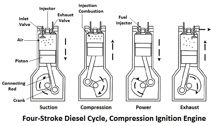
Diesel is injected in the cylinder at the end of compression stroke which itself ignites due to the high temperature of the compressed air. The diesel engine does not have a spark plug. In a four-stroke, diesel cycle compression ignition engine, the four strokes are as follows:
Suction Stroke
- During suction stroke, the piston moves down from the top dead centre position.
- Air is sucked into the cylinder through the open inlet valve which closes at the end o f the stroke.
- The exhaust valve remains closed during this stroke.
Compression Stroke
- The piston moves upwards from the bottom dead centre position.
- Inlet and exhaust valves remain closed. The air is compressed in the cylinder with the upward movement of the piston.
- As the compression ratio in this engine is high (10 to 20), the air is finally compressed to a pressure as high as 40 Kg/cm2 at which its temperature is as high as 100°C, enough to ignite the fuel.
Working Stroke or Power Stroke
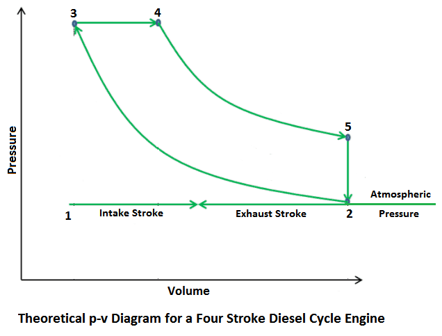
- At the end of the compression stroke, the fuel (diesel) is injected into the hot compressed air where it starts burning maintaining the pressure constant.
- At point 4, the fuel supply is cut-off. Theoretically, the fuel is injected at the end of the compression stroke and injection continued till the point of cut-off.
- Meanwhile, the piston moves from point 3 to 4, and this stroke is called constant pressure stroke.
- In practice, the ignition starts before the end of the compression stroke.
Theoretically, the power stroke from point 4. The hot gases now expand adiabatically to point 5 in the cylinder pushing the piston down. The piston finally reaches to the bottom dead center. Both the valves remain closed during the stroke.
Exhaust Stroke
- The piston moves upward. The inlet valve remains closed and the exhaust opens.
- The maximum burnt gases escape because of their own expansion.
- The upward movement of the piston pushes the remaining gases out through the open exhaust valve. The cycle is thus completed.
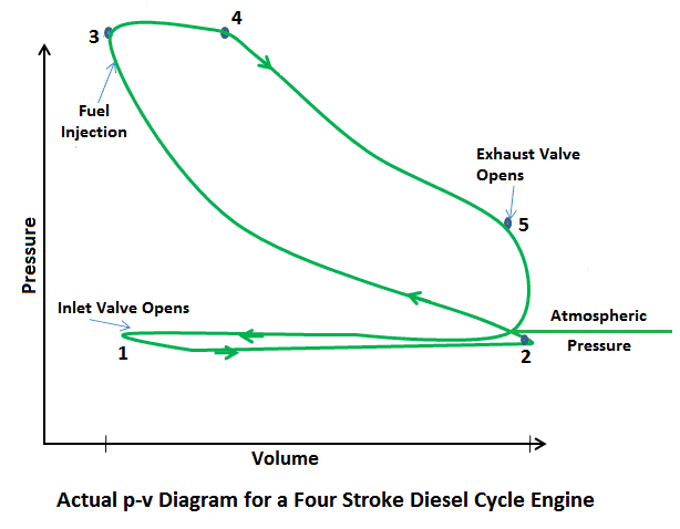
The fig shows the valve timing diagram for a four-stroke diesel cycle engine. Inlet valve opens 10° to 25° in advance of the top dead centre and closes 25° to 50° after the bottom dead centre. the exhaust valve opens 30 ° to 50° in advance of the bottom dead centre and closes 10° to 15° after the top dead centre.
Fuel injection starts 5° to 10° before the top dead centre on the compression stroke and continues up to 15° to 25° after the top dead centre in working stroke, depending upon the speed of the engine.
P-v and T-s Diagram of Diesel Cycle
Let the engine cylinder carry m kg of air at point 1. at this point let P1 and T1 and V1 be the pressure, temperature and volume of the air. Following are 4 stages of an ideal diesel cycle.
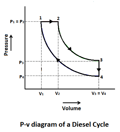
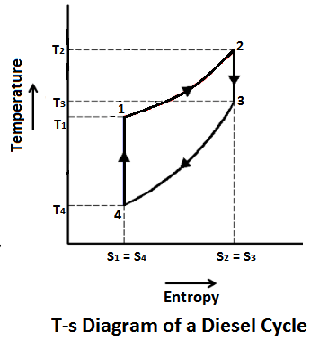
The ideal diesel cycle consists of two adiabatic, constant pressure and constant volume processes. These processes are represented on a P-v and T-s diagram as shown in the Figure.
Read also: Thermodynamic Cycle: Its Classification, Working, Terms Used in Thermodynamics and More.
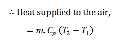
Process 1-2 (Constant Pressure Heating)
The air is heated at constant pressure from initial temperature T1 to a temperature T2 represented by the graph 1-2 in Fig.
The heat is cut off at point 2, so its called cutoff point
Process 2-3 (Adiabatic Expansion)
The air is expanded adiabatically from temperature T2 to a temperature T3 as shown by the graph 2-3 in Fig. In this process, on heat, we absorbed or rejected by the air.
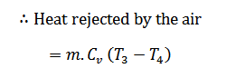
Process 3-4 (Constant Volume Cooling)
The air is now cooled at constant volume from temperature T4 to a temperature T4 as shown by the graph 3-4 in the figure.
Process 4-1 (Adiabatic Compression)
The air is compressed adiabatically from temperature T4 to a temperature T1 represented by the graph 4-1 in Fig. In this process, no heat is absorbed or rejected by the air
We see that the air has been brought back to its original conditions of pressure, volume and temperature, thus completing the cycle.
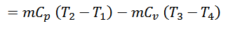
We know that,
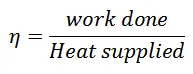
Work done = Heat supplied – Heat rejected
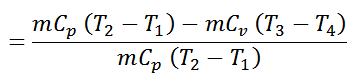
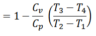
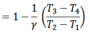
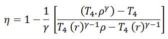
∴ Air standard efficiency
Now let compression ratio,

Cut-off ratio,

Expansion ratio,
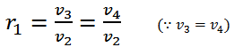
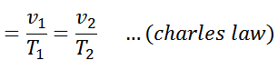
We know for constant pressure heating process (1-2),
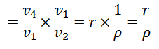
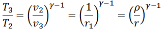
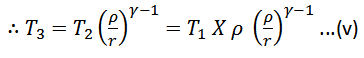
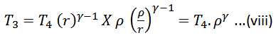
Similarly, in adiabatic compression process (2-3)
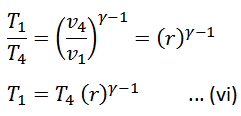
And in adiabatic compression process (4-1),
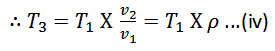
Substituting the value of T1 in equations (iv) and (v)
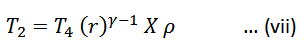
And
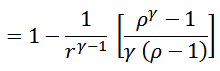
Now substituting the values of T1, T2 and T3 in equation (iii),
Note:
The efficiency of the ideal diesel cycle is lower than of otto cycle, for the same compression ratio.
The diesel cycle efficiency increases with decreases in cut-off and approaches maximum (equal to otto cycle efficiency) than cut-off is zero, i.e, p=1.
That’s it. Thank you guy’s thank you so much for reading this article. If you have any questions about “Diesel Cycle” you can ask in the comment section below. If you like this note please share it with your friends.
Want free PDFs directly to your inbox? Then subscribe to our newsletter.
Download PDF of this article:
Read more about thermodynamic cycles in our blog:
Thanks for explaining the diesel cycle in such detail! I found the P-v and T-s diagram to be particularly helpful in understanding the process. It’s impressive how much more efficient the diesel cycle is compared to the Otto cycle, especially at high compression ratios. I’ll definitely keep this in mind when considering which engine design to use in my next project.
You’re welcome! Glad you found the explanation helpful. Good luck with your project!
Will you send me a copy of 4 stroke diesel engine cycle pdf??
Yeah sure, I have sent you the PDF file to your inbox.