What is an Otto Cycle?
The modern petrol (gasoline) engines operate on the Otto (constant volume) cycle. This cycle was introduced by a German scientist Otto in 1876, although it was described by a French scientist Beande Roches in 1862.
The Otto cycle is an ideal thermodynamic cycle that consists of four-piston strokes: intake, compression, ignition, and exhaust.
Fuel and air are compressed, and ignited by an electric spark, the expansion causes the piston to move, and the piston’s spring action pushes the combusted gas away from the piston.
It is widely used to describe the spark ignition engines seen in automobiles. The Otto cycle aids in the analysis of the engine’s working fluid’s characteristics during the cycle.
Working of Four-stroke Otto Cycle Engine
In a four-stroke Otto-cycle spark-ignition engine, the four strokes are as follows:
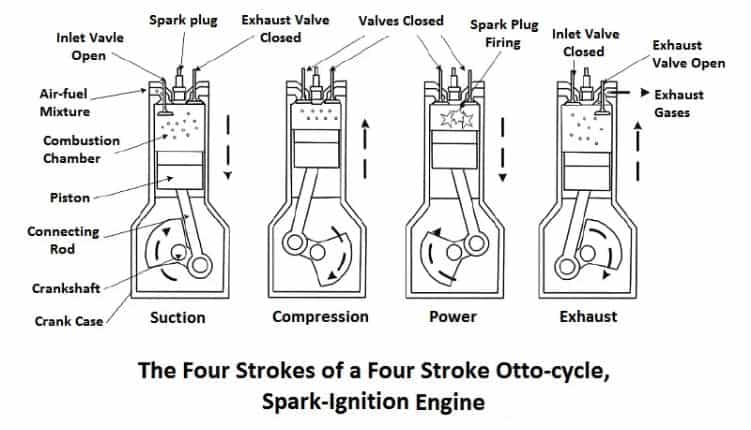
Suction Stroke
- During the suction stroke, the piston is moved downward by the crankshaft, which is revolved either by the momentum of the flywheel or by the power generated by the electric starting motor.
- The inlet valve remains open and the exhaust valve is closed during this stroke.
- The downward movement of the piston sucks the air-fuel mixture in the cylinder from the carburetor through the open inlet valve.
- Here the fuel is petrol mixed with air, broken up into a mist, and partially vaporized in the carburetor.
Compression Stroke
- During the compression stroke, the piston moves upward, thus compressing the charge.
- Ignition and compression also take place during this stroke.
- The heat produced by the compression performs like a mixture of air and petrol inside the cylinder.
- Heat makes petrol easier to burn, while the compression pushes it into closer combination with the air.
- The mixture under compression is ignition by the spark produced by a spark plug, and the combustion is about half-completed when the piston is at the top dead center.
- Both the inlet valves and exhaust valves closed during the compression stroke.
Power Stroke
- The expansion of the gases due to the heat of combustion exerts pressure on the cylinder and piston.
- Under this impulse, the piston moves downward thus doing useful work. Both the valves remain closed during this stroke.
Exhaust Stroke
- During this stroke, the inlet valve remains closed and an exhaust valve opens.
- The greater part of the burn gases escapes their expansion.
- The piston moves upward and pushes the remaining gases out of the open exhaust wall.
- Only a small quantity of exhaust gases remains in the clearance space which will dilute the fresh incoming charge.
Thus, in this type of engine, four strokes of the piston are required to complete the cycle, and the four-stroke makes two revolutions of the crankshaft. The processes are repeated over and over again in running the engine. each alternative revolution of the crankshaft as one power stroke.
Read also: Thermodynamic Cycle: Its Classification, Working, Terms Used in Thermodynamics and More.
The Valve Timing Diagram of a 4-Stroke Otto Cycle Engine
In this engine, the inlet valve opens during the suction stroke and the exhaust valve opens during the exhaust stroke. The exact movement at which each of the valves opens and closes about the position of the piston and crank can be shown graphically in a diagram. This diagram is known as a valve timing diagram.
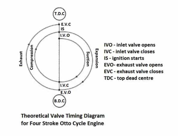
Theoretically, the inlet valve opens exactly at the beginning of the suction stroke and closes at the end of the stroke. Both the valves remain closed during compression and power strokes. The exhaust valve opens exactly at the beginning of the exhaust stroke and closes at the end of the stroke. the theoretical valve timing diagram for a four-stroke Otto cycle engine.
Opening and Closing of Valve During 4 Strokes
The opening and closing of the valve regarding the position of the piston and crankshaft during the four strokes are described as follows:
- Suction Stroke: The inlet valve opens. The piston starts to move downward from the top dead center (TDC) position and reaches to bottom dead center (BDC) position. A fresh charge of air-fuel mixture enters the cylinder. The exhaust valve remains closed.
- Compression Stroke: Both the valves remain closed. The piston starts to move upward from B.D.C, thus compressing the charge until it reaches the T.D.C.
- Working Stroke: Both the valves closed. Sparking takes place from the spark plug which ignites the compressed charge. The piston moves downward from T.D.C and reaches B.D.C.
- Exhaust Stroke: The exhaust stroke opens. The piston moves from B.D.C. and reaches to T.D.C. thus rushing out the burnt gases from the cylinder. The inlet valve remains closed.
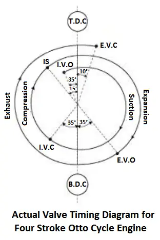
In actual practice, the above cycle is slightly modified. The exact moments of opening and closing the valves about the piston and crankshaft are shown in the figure. This diagram is known as the actual valve timing diagram.
Read also: Carnot Cycle: Principle Processes, Efficiency with [P-v and T-s Diagram]
Inlet valve and Exhaust Valves
Inlet Valve
The inlet valve starts opening 10° to 30° before T.D.C. as measured in degrees of crankshaft rotation. It remains open during 180° of the normal suction stroke and, in addition, 30° to 40° or even 60° after B.D.C., at the beginning of the compression stroke.
The reason for opening the inlet valve before the start of the suction stroke is that the valve is made to open and close very slowly, and this timing of opening the valve is permitted to open sufficiently during the suction stroke.
The valves are arranged to open and close slowly to provide silent operation under high-speed conditions. The column of charge in the inlet pipes requires to be accelerated before the suction stroke starts, so that sufficient charge may enter the cylinder during the suction stroke.
Working of Inlet Valve
As the piston moves downward during the suction stroke, the pressure decreases inside the cylinder which causes the gases to rush in and fill up space above the piston. The pistons reach at the end of the stroke before a complete charge has time to enter through the small inlet valve opening.
Therefore pressure in the combustion space will still be below atmospheric, and the gases will be moving in the direction of the motion of the piston with high velocity. If the inlet valve is closed at this point so that no more charge enters, less charge will remain in the cylinder.
Thus, the inlet valve is made to remain open until the piston reaches a point in its next stroke at which the pressure in the cylinder equals the pressure outside. Also, the actual closing point of the valve coincides with the point when the motion of the rushing charge would reverse the direction.
Timing Data of The Inlet Valve
The figure shows the timing data of the inlet valve for a popular engine. In this engine, the inlet valve starts to open 5° before the top dead center. This pre-admission allows the valve to be open during 5° of the exhaust stroke ( the preceding stroke).
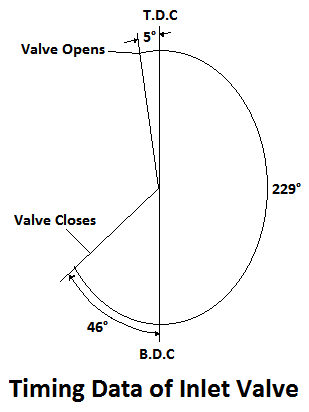
It remains open during 180° of the normal suction stroke, and in addition, during 44° of the beginning of the compression stroke. This gives a total inlet valve opening of 229°of crankshaft rotation.
Exhaust Valve
The exhaust valve starts opening 30° to 60° before B.D.C., remains open during 180° of the normal exhaust stroke, and in addition, 8° to 10° or even 25° after T.D.C. at the beginning of the suction stroke. The reason for opening the exhaust valve before the start of the exhaust stroke is that the gases have an outlet for expansion to begin to rush off their pressure.
This removes the greater part of the gases reducing the amount of the work to be done by the piston on its return stroke. This reduction compensates the waste due to the early release of gases. During the next outward stroke, the remaining gases are forced out through the open exhaust valve. This causes a slight compression of the gases ahead of the piston.
Working of Exhaust Valve
When it reaches to T.D.C. positions, there will be a certain amount of compressed exhaust gases in the clearance space. If the exhaust valve is closed at this point, this amount of exhaust gases will remain in the cylinder.
Thus, the exhaust valve is closed a little after, the end of the exhaust stroke. It may result in drawing the exhaust gases back into the cylinder. But this drawing back is prevented by two conditions,
- Gases under compression exceed the pressure in the manifold and will continue to flow out because of this pressure difference.
- This piston, while at the top of the stroke, moves but very little for 10° to 15° movements of the crankshaft. This does not materially increase the combustion space as shown in fig.
The crankarm is in a position as at A, for a certain number of degrees say 15° movement of the crankshaft, the piston will move upward for a considerable distance. When the crankarms are as at B, for the same 15° turning of the crankshaft, the distance moved by the piston will be less.
When the crankarms are as at C, for the same 15° turning, there is very little upward movement of the piston. It can be seen that between certain points there is practically no motion of the piston travel in the region is called the rock of the piston. Within the region usually, the exhaust valve is closed after the top dead center.
Timing Data of Exhaust Valve
Shown timing data of the exhaust valve for a popular engine. In this engine, the exhaust valve opens 47° before the bottom bead center. this pre-release causes the valve to be open during the last 47°of the power stroke.
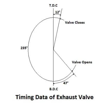
It remains open during the 180° of the normal exhaust stroke, and in addition, during 12° of the beginning of the suction stroke. This gives a total exhaust valve opening of 239° of crankshaft rotation.
Pressure-Volume (p-v) Diagram of Four-stroke Otto Cycle Engine
The ideal Otto cycle consists of two constant volumes and two reversible adiabatic or isentropic processes as shown in PV and T-S diagrams.
Let the engine cylinder contain m kg of air at point 1. At this point, let p1, T1, and V1 be the pressure, temperature, and volume of air.
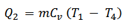
1. Process 4-1 (constant volume heating)
The air is heated at constant volume from temperature T4 to T1.
Heat absorbed by the during tI is a process,
2. Process 1-2 (Adiabatic or isentropic expansion)
The air is expanded reversibly and adiabatically from an initial temperature of T1 to a temperature of T2. In this process, no heat is added or rejected by the air.
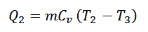
3. Process 2-3 ( constant volume cooling)
The air is cooled at constant volume from temperature T2 to temperature T3.
Heat is rejected by the air during this process.
4. Process 3-4 (Adiabatic or isentropic compression)
The air is compressed adiabatically from temperature T3 to temperature T4. In this process, no heat is added or rejected by the air. The air has been brought back to its original conditions of pressure, volume, and temperature.
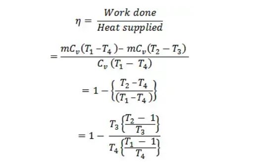
Work done = Heat supplied – Heat rejected
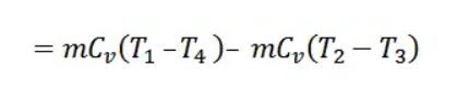
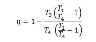
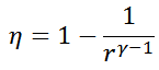
Air standard Efficiency,
Consider adiabatic expansion 1-2
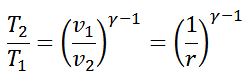
Where, r = Expansion ratio
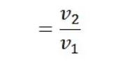
Consider adiabatic compression 2-3
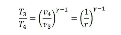
Where r = Compression ratio

From equation (2) and (3)
Since the right side is the same,

Interchanging terms

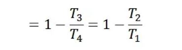
Substituting the value of T2/T3 in equation 1
Note
It is to be noted that in the theoretical p-v diagram, every corner is sharp which represents the opening and closing of the valve instantaneously. Also, the suction and exhaust take place at atmospheric pressure.
The valve’s opening and closing cannot occur instantaneously but take some time, by which every corner in the p-v diagram will be round, as shown in the actual p-v diagram. Also, the suction takes place at a pressure slightly lower than the atmospheric pressure due to the resistance of the inlet valve of the entering charge.
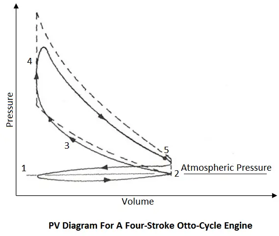
The exhaust takes place at a pressure slightly higher than the atmospheric pressure due to the resistance of the exhaust valve to the exhaust gases. This gives an area, in the form of a small loop, and indicates the pumping loss of the engine. This area is treated as negative and hence subtracted from the area of the larger loop which is treated as positive, giving us the network done during the cycle.
Advantages of Otto Cycle
These cycles are the most widely utilized and reliable in many IC engines. There should be some benefits to this broad use.
- High reliability in terms of performance.
- The cycle works best with light cars that use gasoline engines.
- Affordable production costs for engines built on this cycle.
- The high power-to-weight ratio of engines is built using the Otto cycle principle.
Disadvantages of Otto Cycle
Due to a few drawbacks, the cycle is not as widely used in different applications.
- Only light and medium-duty petrol cars can use the Otto cycle.
- Diesel engines cannot use this cycle.
- Because of its lower efficiency compared to the Carnot cycle, it is not utilized in power plants.
Application of Otto Cycle
Despite its drawbacks, the Otto cycle has numerous uses. Following are some of the applications.
- The Otto cycle is used by nearly all of the current cars on the road to turn energy into work.
- When 2-stroke engines started to lose favor, the Otto cycle became more and more common in the 4-stroke engine class.
- These engines can be found in automobiles, motorcycles, mopeds, ships, trains, and even airplanes.
That’s it, thanks for reading. If you have any questions on “Otto Cycle Engine” ask in the comments. If you found this article helpful please share it with your friends.
Want free PDFs direct to your inbox? Then subscribe to our newsletter.
Download PDF of this article:
More about the thermodynamic cycles: