Electrical Comparator
The electrical comparator works on the principle that the mechanical displacement is converted into an electric signal. Hence they are known as an electro-mechanical measuring system.
The block diagram shows the electromechanical measuring system.
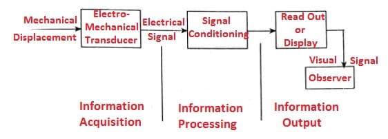
Simple Electrical Comparator Electro Limit Gauge
Any electrical comparator works on the principle of electron limit gauge or measuring head the setup is as shown as below:
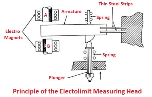
The vertical movements of the plunger are transmitted to an armature, which is suspended, on thin metal strips. At the left-hand side of the armature, we observe that armature lies between two electromagnetic coils A and B, which form two arms of an A.C. bridge circuit.
The movement of the armature between the two electromagnetic coils sets up out of balance effects, which are recorded by a micrometer. If micro-ammeter is calibrated in terms of the displacement of the plunger, direct reading of small movements can be achieved.
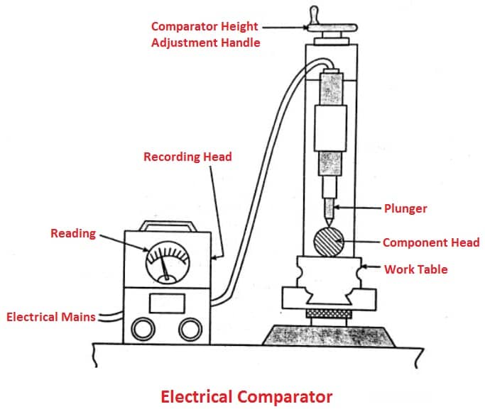
The complete instrument is shown in the figure above and fluctuations up to 15% have no effect on the accuracy.
Read also: Optical Comparator: Types, Working, Advantages and More
Linear Variable Differential Transformer (LVDT)
LVDT is the most popular electro-mechanical device used to convert the mechanical displacement into an electrical signal.
A differential transformer is one of the most useful variable inductance transducers, it provides on alternating current voltage output proportional to the displacement of a core passing through the windings. It is a mutual inductance device making use of three coils arranged in the figure shown.
It consists of an insulating foam which is wound by the primary coil and two secondary coils kept al an equal distance from the primary coil.
Constant AC voltage is supplied to the primary coil and the output is obtained from the two secondary coils.
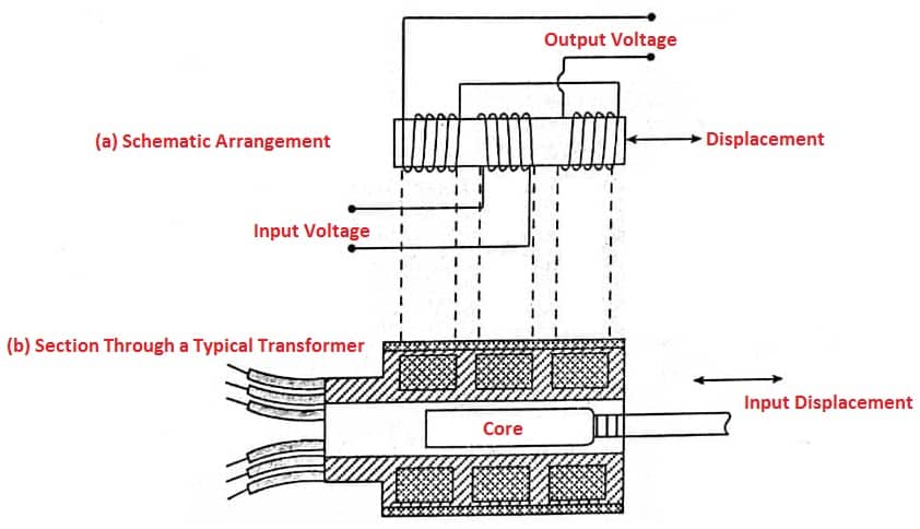
The primary and secondary coils are wound around the core made of nickel-iron alloy to improve magnetic impermeability and it is annealed. When this core has moved the inductance of both primary and secondary voltages varies which determines the voltage induced in the primary and secondary coil. Thus the output is directly proportional to the core displacement. It is widely used for the on-fine machining and it has high reliability.
Fig. (c) shows the characteristics obtained by plotting the output voltages versus core displacements. Within the limits on either side of the null position, the core displacements result in a proportional output. This linear range depends upon the length of the secondary coil.
Beyond the proportionality limit, the output increases at a decreasing rate until it reaches a max from which it drops again to the balanced condition when the core is out of the transformer.
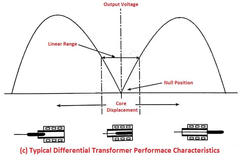
All commercial differential transformers are designed to operate only in the linear range and are known as linear variable differential transformers (LVDTs).
They operate on a supply voltage of 6.3 volts at 60 cps. LVDTs are designed for the max displacement of 25 mm. The sensitivity decreases with higher frequencies and with an increased number of turns on the coils.
Read also: Mechanical Comparator: Types, Design, Working, Advantages and More
Advantages of LVDT:
The main advantages of LVDT over other transducers are:
- LVDT cannot be overloaded mechanically because the core is completely separable from the rest of the equipment.
- It can be used as a primary detector transducer, as it converts mechanical displacement into electrical voltage.
- It is relatively insensitive to high or low temperatures and to temperature changes.
- The high output obtained can be used without intermediate amplification
- It is reusable and of reasonable cost.
Disadvantages of LVDT:
- It cannot be used in the area of dynamic measurement since the core is of considerable mass as compared to the strain gauges.
- If 60 cycles per second supply voltage are used then it becomes a limiting factor as for as dynamic measurement is concerned.
- If the direction from the null point is to be indicated then the advantage of the sample circuit arrangement is lost.
Advantages
- The electrical comparators have a small number of moving parts hence high accuracy can be achieved.
- It is possible to get a very high magnification and the same instrument may have two or more magnifications, thus the same instrument can be used for various ranges.
- The mechanism carrying the pointer is very light and not sensitive to the vibrations.
- The measuring unit is compact and it is not necessary that the indicating instrument is close to the measuring unit, rather it can be remote also.
- An instrument is operated on AC supply, the cyclic vibration substantially reduces errors due to shelling friction.
Disadvantages
- This Comparator requires external sources of energy to operate i.e., electrical supply. Thus the Nuctuation in voltage or frequency of electric supply may affect the result.
- Heating of coils in the measuring unit causes chances of zero drill and alter the calibration.
- If a fixed scale is used with a moving pointer then with high magnification very small range is obtained.
- These comparators are costlier than mechanical comparators.
That’s it, Thanks for reading. If you have any questions about “Electrical Comparator” you can ask in the comments. If you like this article please share with your friends.
Read Next: