In this post, you’ll learn what is mechanical comparator and its types, construction, working, and advantages.
What is a Mechanical Comparator?
A mechanical comparator is a measurement device that uses mechanical components, such as racks, pinions, gears, and levers, to obtain magnification. These types of devices are mostly employed to increase the instrument’s precision by magnifying the movement of the means.
Mechanical comparators are very accurate measuring tools that are widely utilized in many sectors for quality control and dimensional inspection.
These comparers are mechanically designed with a sturdy stage for positioning the workpiece, adjustable lenses or mirrors for varying the amount of magnification, and a profile projector screen for clear and precise visualization of the results.
These comparators come in a variety of forms that provide the customer the freedom to choose the best and most affordable option for a given metrological application.
Parts of Mechanical Comparator
In mechanical comparators the required magnification is obtained by mechanical linkages and other mechanical devices, among which the main types are discussed below:
#1 Rack and Pinion
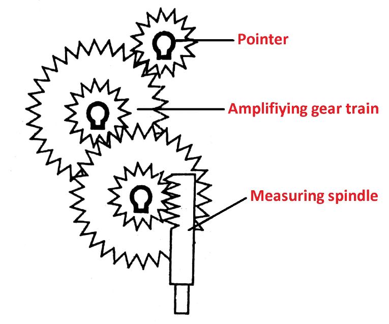
Here the measuring spindle is integral with a rack, and engages a pinion which expands the movement of the plunger by a gear train.
#2 Cam and Gear Train
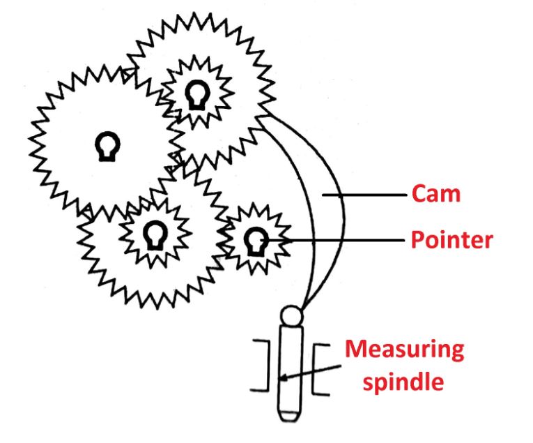
Here the measuring spindle acts on a cam which transmits the motion to the amplifying gear train.
#3 Lever with Toothed Sector
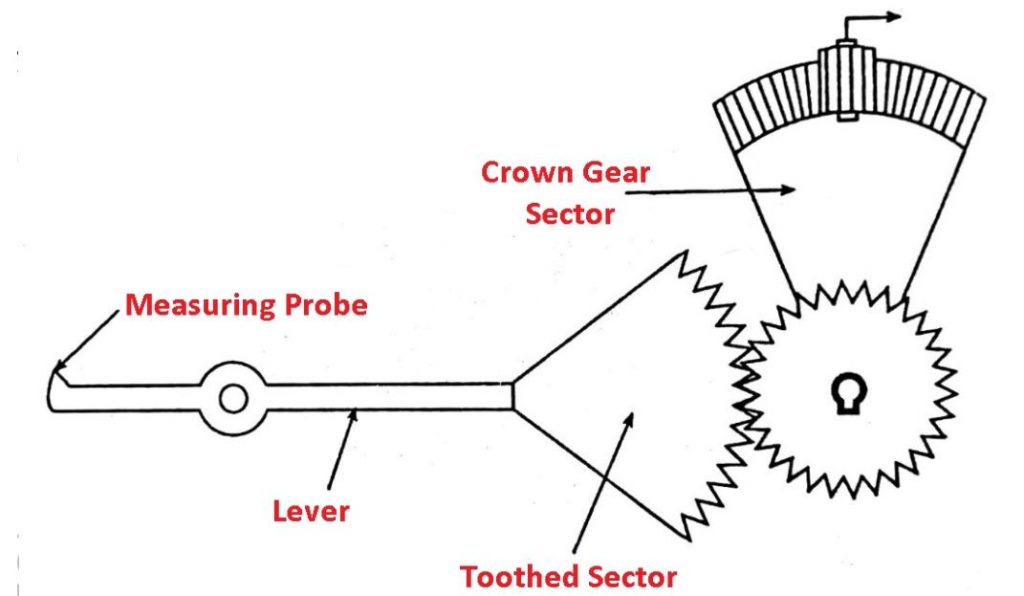
Here the lever with the toothed sector at its end engages a pinion in the hub of a crown gear sector which further meshes with a final pinion to produce an indication.
#4 Compound Levers
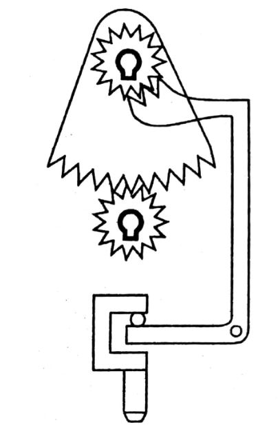
Here levers forming a couple with pound action are connected through segments and pinion to produce final pointer movement.
#5 Twisted Taut Strip
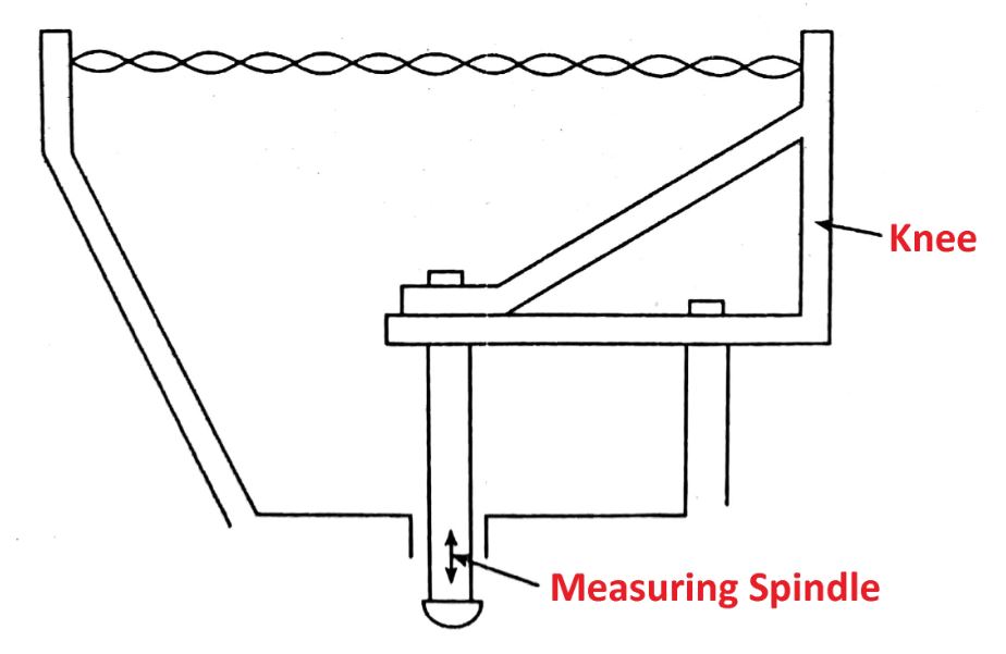
In this, the measuring spindle movement tilts the knee creating straining which further forms the twisting taut band to rotate proportionally. The motion of strip is displayed by the attached pointer movement.
#6 Lever Combined with Band Wound Around Drum
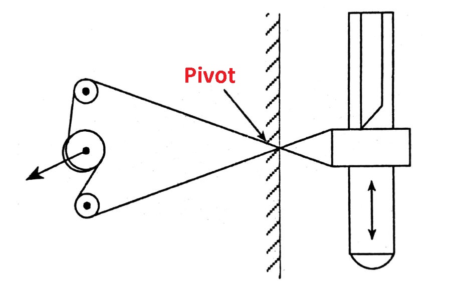
In this, the movement of the measuring spindle tilts the joined block, creating a swing of a fork which causes rotation of the drum.
#7 Reeds Combined with Optical Display
In this, the parallelogram reeds are used to transfer measuring spindle movement to a deflecting reed whose extension provides a target used in the optical path.
Read also: Definitions and Terms Applicable to Mechanical Measurements
Working Principle of Mechanical Comparator
A mechanical comparator works by using mechanical techniques to magnify tiny deviations. In all mechanical comparators, gear train levers impact the magnifying technique of the indicator’s tiny movement.
The magnifications of these comparators vary from 300 to 1000. The mechanical comparator, sometimes referred to as the “microcator,” is a tool for linear measurements made using the relative contact method.
Types of Mechanical Comparator
Following are the Five types of mechanical comparators:
#1 The Johansson Mikrokator
This is the simplest method for obtaining mechanical magnification, of order x 5000. It was designed by H. Abramson and manufactured by Johansson Limited company. The setup is as shown in the figure below:
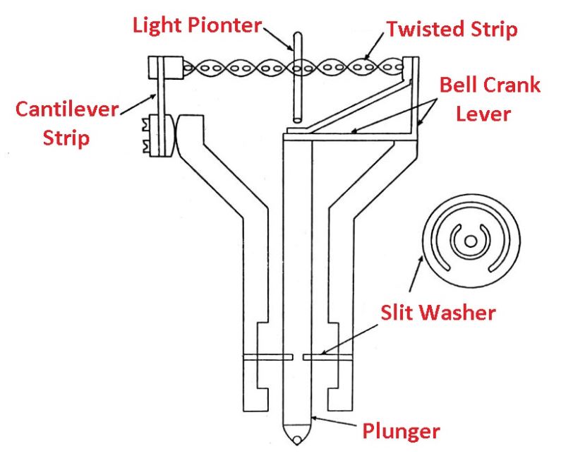
The construction consists of a thin metal strip, glass pointer, bell crank lever, cantilever strip, and a plunger. The strip is twisted in opposite directions so whenever the strip is pulled it will rotate. The thin glass pointer is attached to the center of the twisted strip.
One end of the strip is connected to the measuring plunger which is fixed and the other end is connected to the adjustable cantilever strip. The bell crank lever is formed of flexible strips with stiff diagonals.
The length of the cantilever can be varied to adjust the magnification. According to the variation in the dimension of the part to be measured, the plunger moves up and down.
Working:
Mikrokator Comparator works on the principle of a button spinning on a loop of string. Whenever the measuring plunger moves up or down, with the help of a bell crank lever, the strip changes its length because the elbow acts as a bell crank lever.
Thus whenever the strip is stretched, the glass pointer rotates to an amount equal to the change in the length of the strip or plunger movement.
Magnification can be determined by using the following relation.

Where,
- l = length of the twisted strip
- θ = Twist of mid-point of strip w.r.t. the end
- n = number of turns in the given length of strip 1.
- w = width of the twisted strip.
From the above relation, magnification is directly proportional to length but inversely proportional to the square of the width and the number of turns. Hence thin rectangular strips are used to obtain high magnification in Johansson Mikrokator Comparator.
#2 Reed Type Mechanical Comparator:
These types of Mechanical comparators are used for magnifying the small motions of the spindle, where the amplification obtained is less than 100.
Construction:
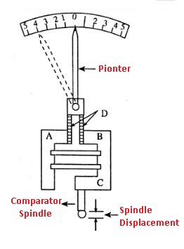
It consists of a fixed block A which is rigidly fastened between floating block B and the gauge head case which carries the gauging spindle and is connected horizontally to the fixed blocks by reeds C. Vertical needs are attached to each block with top ends joined together. It contains a pointer, which is the most important item.
This setup is shown in the figure:
Working:
The reed mechanism is considered to be a frictionless device. Here the linear motion of the comparator spindle moves the floating block upward which raises the vertical reeds, resulting in the deflector of the pointer. The amount of deflection is directly proportional to the distance of the spindle displacement.
#3 Dial Indicator
Dial Indicator is the most commonly used mechanical comparator. It works on the principle of Rack and pinion system i.e., the linear movement of the spindle is magnified by rack and pinion arrangement.
It consists of a robust base whose surface is flat and a pillar supporting a bracket in which a spindle is fitted with a pinion and a dial scale.
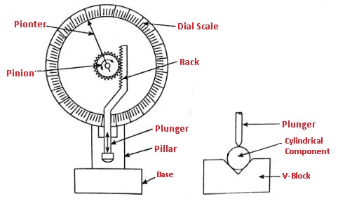
By the use of slip gauges, the dial scale is set to zero representing the basic size of the part. This is used for the inspection of small machined parts. This type of comparator is used with different attachments.
So that it may be used for a large number of works. For example, a V-block attachment can be used for checking out of roundness of a cylindrical component as shown in the figure.
#4 Sigma Comparator
Sigma Comparator is also a frictionless device for magnifying small motions of the spindle.
Construction:
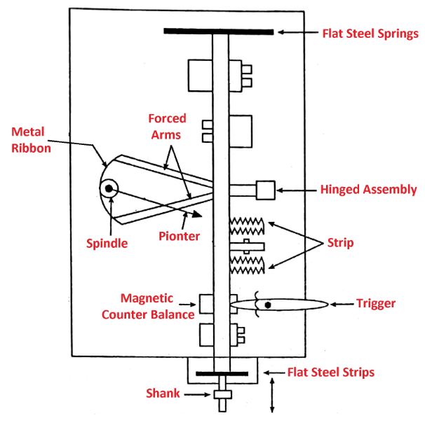
- It consists of a vertical beam mounted on flat steel springs and this beam is fixed to the backplate by a fixed member and one end of the vertical beam is made to come in contact with the measuring parts. The stoppers are used to restrict the movement.
- A hinged arrangement is also fixed to the vertical bar which will also carry the indicator. All these basic arrangements are made to get the correct and accurate value.
Working:
- As the lower portion of the bar moves up and down, the hinged portion with the indicator shows the deflection. This is available in 600, 300, and 150mm and magnification of 5000, 3000, 1500, and 1000.
- To have frictionless linear movement the plunger is mounted on a pair of slit diaphragms. A knife edge is attached to it and has the face of a moving member of a cross-strip hinge.
- The cross-strip hinge consists of a moving component and a fixed member which are connected by these flexible strips alternatively at a right angle to each other. Thus when an external force is applied to the moving member, it will pivot, as would a hinge about the line of intersection of the strips to the moving member an arm of Y shape having length ‘l ’ is attached.
- If the distance of the hinge from knife-edge is a then the magnification of the first stage is R/a. A phosphor bronze strip is attached to the two extremities of the arm Y and is passed around a radius ‘r’ attached to the pointer spindle. If the length of pointing is ‘R‘ then R/r is the second stage of magnification. Thus total magnification is (R/a)(R/r)
The Important Features of the instrument are:
a) Safety: The knife-edge moves away from the moving member of of the high and is followed by it, therefore, if the too robust movement of the plunger is made due to shock load, that will not be transferred by the movement.
b) Dead beat readings: The pointer is caused to come to rest, with little or no oscillation, by mounting the pointer spindle on a non-ferrous disc moving in the field of a permanent magnet.
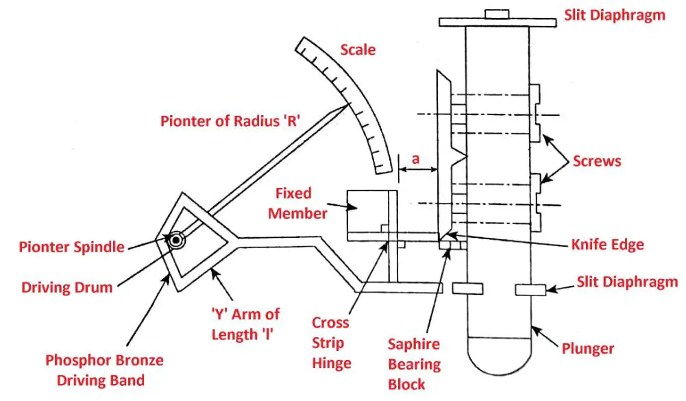
c) Parallax: The pointer tip is turned through 90° and carried across its end a small ‘tee’ piece which moves in the slot and thus lies in the plane of the scales. As the pointer and scale lie in the same plane the parallax error is eliminated.
d) Constant Pressure: The constant measuring pressure over the range of the instrument is obtained by the use of a magnet plunger on the frame and keeps the bar on the top of the plunger.
Whenever the plunger is raised the force required increases but the keeper bar approaches the magnet and the magnetic attraction between the two increases. Therefore as the deflecting force and assistance by the magnet increases and total force remains constant.
#5 Brookes Level Comparator
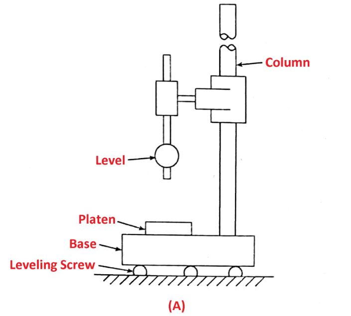
This type of mechanical comparator consists of a spirit level. It works on the principle of displacement of the bubble in a sensitive tube.
It consists of a massive base on which a sensitive level tube and rotatable disc are placed, which has mutually parallel surfaces.
While operating the end of the bubble is brought to the center of the scale, by using a block gauge or combined block gauge and length bar.
The standard (S) and the gauge to be compared (G) are wrung to the platen and the ball feet of 200 mm Centres nest on the gauges which form the bridge as in Figure (b). Then the position of the end bubble against the scale is noted, which will be the first reading.
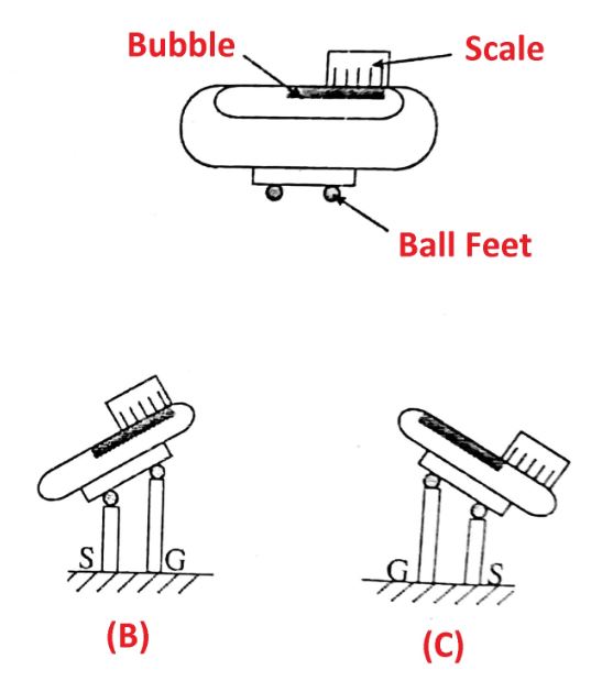
Then the level is raised and the platen is rotated through 180° and the second reading is noted down as in figure (c). The displacement of the bubble along the scale represents twice the difference in length between the gauges.
Thus δh = 1/2
Where,
- δh = length difference between gauges
- l = bubble displacement
Advantages
The following are some benefits of mechanical comparators.
- Mechanical comparators are cheaper as compared to other amplifying devices.
- These comparators don’t require any external supply of electricity or air.
- These comparators have a linear scale, for easy understanding.
- Generally, they are robust, compact, and easy to handle.
- They are suitable for ordinary workshop conditions and they are portable they can be issued from a store.
Disadvantages
The following are some drawbacks of mechanical comparators:
- The mechanical comparators have more moving parts, due to which the friction, wear and tear are a high and low inaccuracy.
- Any negligence in moving parts reduces accuracy.
- The mechanism has more inertia, which causes the instrument to be sensitive to vibrations.
- The range of the instrument is limited as the pointer moves over a fixed scale.
- Parallax error is high as the pointer moves over a fixed scale.
- Highly difficult to incorporate arrangements for adjusting the magnification.
Applications
Mechanical comparators can be used for the following purposes:
- The primary purpose of the reed-type mechanical comparator is to measure the workpiece’s dimensional deviation from the standard specifications.
- Comparator is employed in laboratory testing and mass production for analytical applications.
- This comparator is mostly utilized in various manufacturing organizations for cylindrical automotive components, bearing cage races, inner rings, and outer rings.
- Micators, or small spring measuring heads, minicators, or spring-lever indicators, and opticators, or spring-optical measuring heads, all use the mechanical comparator mechanism.
- A mechanical comparator employs mechanical and optical components to increase the plunger’s movement.
- Comparators measure surface roughness by measuring the difference between standard and measured values.
Closing It Up
That’s it, thanks for reading. If you have any questions about “Mechanical Comparator” you can ask in the comments below. If you like this article please share this with your friends.
Want free PDFs direct to your inbox? Then subscribe to our newsletter.
Read Next:
- Bevel Protractor: Types, Parts, Reading, Applications and more
- Vernier Caliper: Parts, Types, Working Principle, Least Count, Errors
- Micrometer Screw Gauge and Types of Micrometers
References or External Links: