In metrology, the pneumatic comparator is a precise instrument. It is used to determine the accuracy of a given component by comparing its dimensions to the actual functioning standard.
It is a type of indirect precision measurement. Since it will not measure the dimension, it will specify the dissimilarity within measurement between the supplied component & working standard.
A comparator can be of several types based on the application, such as electric and electronic, optical, electromechanical, mechanical-optical, pneumatic, multi-check, fluid displacement, projection, automatic gauging & mechanical comparators.
In this article, we will be going to learn about the pneumatic comparator. So, let’s get started.
What is a Pneumatic Comparator?
In pneumatic comparators, air is used as a means of magnification. The term ‘Pneumatic’ in pneumatic comparator refers to ‘air’. This comparator’s main purpose is to examine the dimensional variance between the standard workpiece and the workpiece to be measured.
Pneumatic comparators work on the principle that if an air jet is in close proximity to a surface the flow of air out of that jet is restricted. Which results in the change of pressure in the system supplying the jet.
The design for explaining the principle of the pneumatic comparator is as shown below:
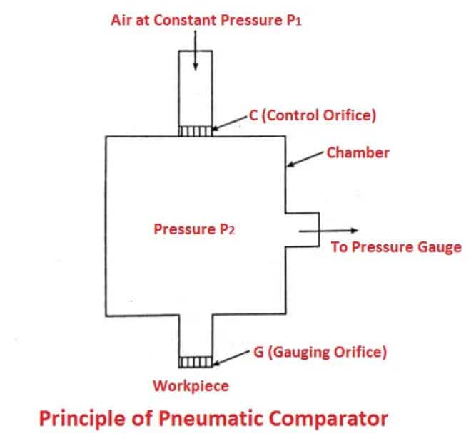
The arrangement shows a chamber fitted with a control orifice (C) and a gauging orifice (G) through which air flows from a supply at constant pressure (P1).
If the size of the control orifice ‘C’ remains constant, any variation in the size of the gauging orifice ‘G’ will cause an alteration in the pressure (P2) in the chamber.
This pressure variation is measured by a pressure gauge of suitable sensitivity either using a manometer, Bourdon gauge, etc. The size of the gauging orifice (G) varies as the distance of the workpiece from the gauging orifice (G) alters.
Read also: What are the different types of Mechanical Comparators?
Characteristics of Pneumatic Comparators
The following are the main characteristics of the pneumatic comparator:
- A very high amplification of order into 30,000 is possible. Hence it can be used to measure diameters length, squareness, parallelism, concentricity, taper, centre distance between holes, etc.
- There is no wear on the gauge because there is no physical contact either with the setting gauge or the part being measured.
- The story of size, taper, straightness, camber bell mouth, etc., will be given whenever internal dimensions are measured.
- It is independent of operator skill.
- High-pressure air gauging can be done with cleaning of the parts which helps to eliminate errors due to dirt and foreign matter.
- To prevent part deflection gauging pressures can be kept low.
- It is an accurate, flexible, reliable, universal, and speedy device for inspecting parts in mass production,
- The total cost of the gauging heads is less.
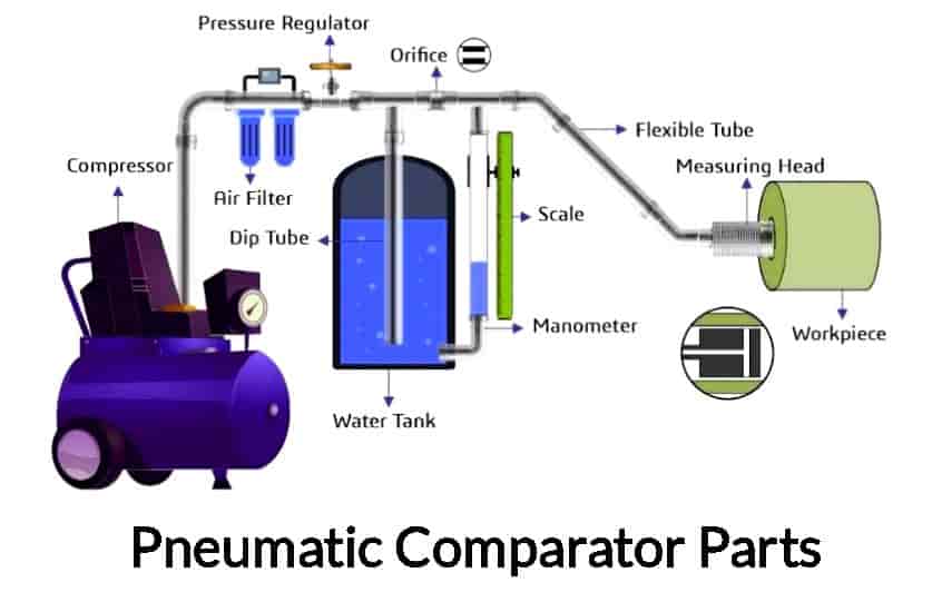
Parts of Pneumatic Comparator
The pneumatic comparator is made of a few key components, some of which are listed below.
#1 Compressor
The compressor generally decreases the volume of a substance by increasing its pressure. The substance is generally a gas.
So, compressors are utilized in comparators, natural gas processing plants, petroleum refineries, and various plants such as petrochemical, chemical, and major industrial operations.
#2 Air Filter
A common type of air filter serves as a safeguard against various pollutants including dust, sand, and dirt damaging any engine. However, if it’s blocked, your engine’s efficiency will suffer.
In a similar manner, the filter and CU (compressor unit) are connected in this form of comparator. When removing air dirt particles, the air filter is really helpful. In this, the compressor compresses the air.
#3 Pressure Regulator Unit
It regulates the gas or liquid pressure to a desired level. In this comparator, a regulator is used to control the compressed air pressure coming from the filter.
#4 Dip Tube
It is an internal pipe that is set up in the airline near the pneumatic comparator’s pressure regulator. These tubes are generally made of polypropylene or polyethylene. This tube is dipped straight into the tank.
The upper chamber refers to the area where this tube and the airline link. It is mainly used for withdrawing liquid products from liquid cylinders like propane, carbon dioxide, liquid hydrocarbon blends, ammonia, or other refrigerants.
#5 Tank
In this comparator, it is a specific kind of metal cylinder positioned at the base of the upper chamber, holding the dip tube inside of it.
The air pipe divides into two channels after the air supplies have passed through the air filter. Therefore, some air will enter the water tank and some will enter the orifice.
#6 Manometer Tube
It is a U-tube column that is vertical or sloped. Therefore, this comparator’s tube is positioned vertically and parallel to the bottom of a tank.
A manometer tube’s exit is located in the second chamber, which resembles an orifice. To show the pressure, a reference liquid is placed within this tube.
#7 Orifice
It is a flow restrictor that regulates the flow of liquid, gas, and air through many systems, including ventilators, comparators, etc. The comparator’s orifice is situated in the airline between two dip and manometer tube intersections. It enables a stable air supply at a certain pressure.
#8 Flexible Tube
It usually serves to link taps to stop cocks. These tubes come in a range of lengths. Within the airline, a flexible tube is employed to hold the measuring head.
In this way, the tube’s starting point is secured with a subsequent chamber that serves as both a manometer and an airline connector, and the endpoint is connected via a gauging or measuring head.
#9 Measuring Head
It is linked by an orifice via a flexible tube. In this comparator, the measuring head is connected to the pneumatic hose or flexible tube.
There are two restricting jets inside the measuring head. This assists in checking for irregularities or unevenness in the workpiece.
#10 Measuring Scale
It is a device used to calculate, count, or compare an unknown length to a standard length. The measuring scale is calibrated and parallelly linked to the manometer tube. This scale’s primary use is for measuring the fluid dislocation that occurs inside the tube.
Working Principle
The working principle of the Pneumatic comparator is the change of pressure created by the airflow. When air escapes under stable pressure through two orifices, the pressure between them is mostly determined by their cross-sections. Therefore, one’s dimension is maintained while the pressure on the other one varies according to that dimension.
Working of Pneumatic Comparator
The pneumatic comparator functions by having a water tank that is filled with water to a specific level. The calibrated manometer is then vertically attached to the tank. Both the water level and the manometer must be equal in the water tank. They are both adjusted using a workpiece.
In order to compress the air, a compressor is utilized at its highest pressure. As a result, an air filter and pressure regulator work together to filter and regulate the pressure of the air. The air that has been filtered will be delivered through a dip tube that is submerged in a tank.
During this time, compressed air flows through the opening of the control orifice at equivalent pressure. Once air has passed through the control orifice or CO, velocity will increase and pressure will stabilize at the same time. The air is delivered through a flexible tube or pneumatic hose at a high velocity before reaching the measuring head.
Due to the expansion of air inside, the head of water in the dip tube is kept steady. The extra air will escape from the tank as air bubbles. At constant pressure, the air escapes through a measurement jet in the measuring head. When the workpiece is uniform, air constantly escapes through the measurement jet.
Simultaneously, the water level in the tank and the manometer tube will be aligned. Whenever there is an irregularity in the workpiece, especially in the measuring jet, a certain back force will occur.
During the manometer operation, the water level will drop due to induced back pressure. As a result, the amount of water change can be expressed as dimensional variation or any irregularities inside the workpiece relative to a normal workpiece.
Types of Pneumatic Comparator
Following are the types of pneumatic comparator:
- Flow or velocity type
- Back pressure type
- Differential type
Classified on the basis of the physical phenomenon on which the pneumatic comparator works.
#1 Flow or Velocity Type Comparator/Force Flow Air Gauges
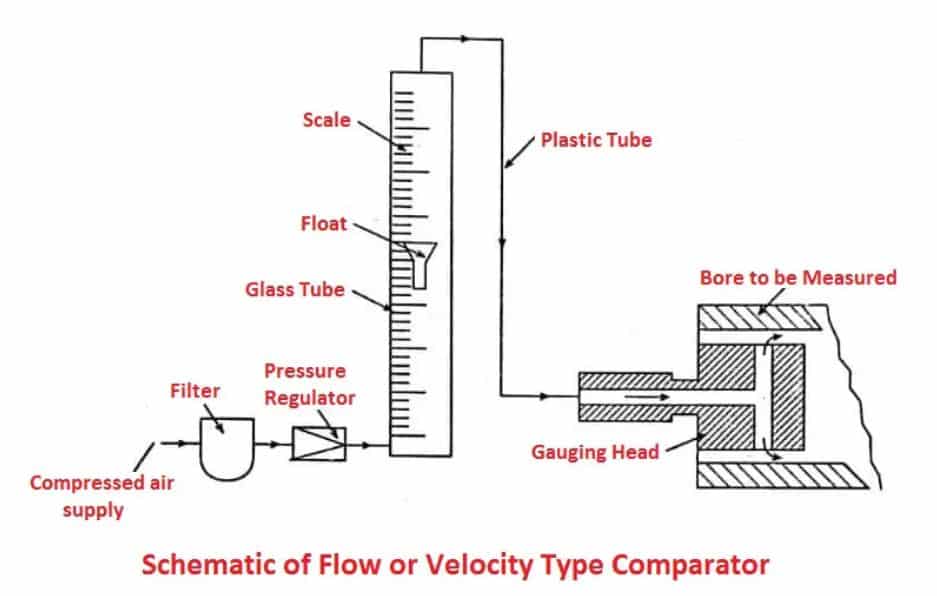
This types of pneumatic comparator operates by sensing and indicating the momentary rate of airflow. The flow could be sensed by a glass tube with a tapered bore, mounted over a graduated scale, inside the bore afloat is liſted by the airflow.
In this setup, the compressed air after filtering and pressure regulating unit flows through a glass tube containing a small metal float.
The compressed air then flows through a plastic tube, which is located in the opposite direction with two identical holes to escape the air.
The position of the float depends upon the amount of air flowing through the gauge head, which in turn depends upon the clearance between the bore to be measured and the gauging head.
#2 Back Pressure Types Pneumatic Comparator
The principle of back pressure pneumatic comparator can be explained by the following setup.
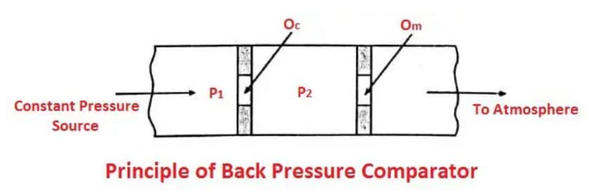
The air from a constant pressure source lows to the atmosphere through two orifices ‘Oc’ and ‘Om’ as shown in the above figure.
If P1 is the pressure upstream of the first orifice and P2 is the pressure between two orifices both measured with reference to the atmospheric pressure as a datum.
The relationship between P1 and P2 depends upon the relative sizes of the two orifices. P2 becomes equal to P1 when Om is blocked and tends to zero as Om is increased indefinitely.
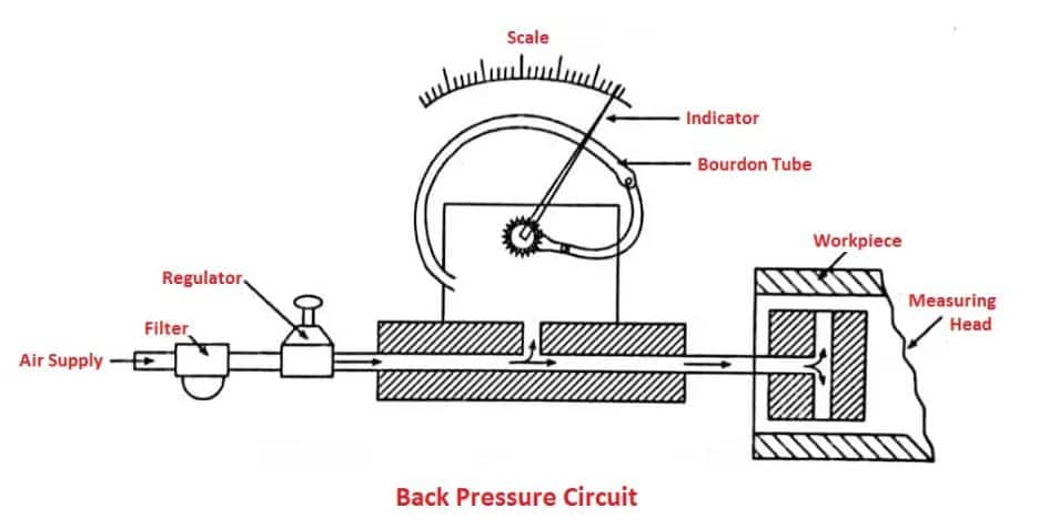
The figure below shows the basic back pressure circuit, in which a bourdon tube, bellows, or diaphragm deflects according to the backpressure change built up in the cult when the workpiece is placed over the measuring head. The deflection is amplified rever and gear arrangement and indicated on a dial.
#3 Differential Type Pneumatic Comparator
Differential pneumatic comparators include a pressure regulator, compressor, air filter, control orifice, zero setting valve, pressure indicating device & measuring head.
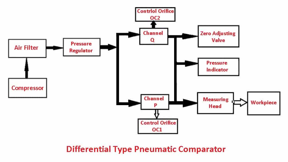
In this comparator, the air is compressed and then allowed to pass through the air filter and pressure regulator. Afterward, the air pressure is created and stabilized. The air in the split channel flows at a constant pressure.
Air flows through control orifice1 (OC1) & reaches the measuring head through channel ‘P’ at one end. The air supplies also travel through the control orifice 2 to a zero adjusting valve via the channel.
The pressure-indicating gadget is situated inside the airline. Here, the airline links the P and Q channels together. First, it is adjusted using a workpiece. When this measuring head travels toward the workpiece, the measuring device’s pointer begins to turn away.
A decrease in permission or constraint between the workpiece and measuring head will increase the pressure within the system, which leads to deflection.
Solex Pneumatic Gauge
This instrument is produced by Solex Air Gauges Ltd and is designed for internal measurement, but with a suitable measuring head, it can be utilized for external gauging.
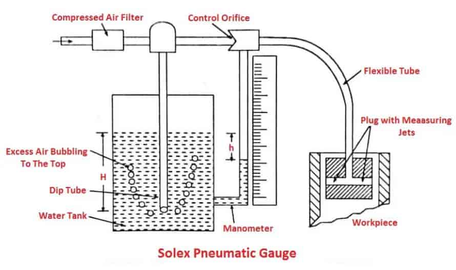
In the above setup, the high-pressure air or compressed air after filtering, through the flow valve. There is a link in which water is filled up to a certain level and a dip tube is immersed into it up to a depth corresponding to the air pressure required, which is represented by ‘H’.
As the air is sent at a higher pressure than required, some air will leak out from the dip tube and bubble out of the water and the air moving towards the control orifice is at the desired constant pressure ‘H’.
The air at reduced pressure then passes through the control orifice and escapes from the measuring jets. The backpressure in the circuit is indicated by the head of water displaced in the manometer tube; which is denoted as h. This instrument is able to measure the accuracy of microns.
To measure the concentricity, the workpiece may be revolved around a measuring gauge, if there is no change in reading, then it is a perfectly round hole.
Similarly, the diameter can be noted down at several places along the length of the bore and thus tapering of a hole is determined.
Thus it is best suited for measuring the roundness and taperness of cylinder bores and gun barrel bores.
Advantages of Pneumatic Comparators
The following are the advantages of a pneumatic comparator:
- In pneumatic comparators, the gauging member does not come into contact with the part to be measured and hence practically no wear and tear takes place on the gauging member.
- These have a very small number of moving parts and in some cases none. Thus accuracy is high due to the absence of friction and less inertia.
- It is possible to have a very high degree of magnification.
- The measuring pressure is very small and the jet of air helps to clean dust, if any, from the part measured by the jet of air.
- Very suitable to measure the diameter of holes when diameters are small as compared to the lengths.
- The best method of measuring the orality and taperness of a circular bore.
- It is possible to have a very high degree of magnification.
- It features a powerful magnification of 30000:1.
Disadvantages of Pneumatic Comparators
The following are the disadvantages of pneumatic comparators:
- It requires elaborate auxiliary equipment such as an accurate pressure regulator.
- The scale is generally not uniform.
- The device is not portable and is rather involved in many industrial applications.
- In comparison to an optical comparator, this comparator has a slower response time.
- It requires a variety of measuring heads to inspect various workpieces.
- This comparator’s accuracy is primarily affected by changes in humidity and temperature.
- This comparator needs various gauging heads or other dimensions.
Applications of Pneumatic Comparators
The following are the applications of a pneumatic comparator:
- The internal diameter of cylinder workpieces can be easily found by this pneumatic comparator.
- It is mostly used to determine how much the length differs from the starting points.
- When it’s necessary to test a lot of workpieces or cylinders, this comparator is used.
- The main purpose of these comparators is to quickly look over a large number of equal dimensions.
- These are frequently utilized to automatically regulate the component size, similar to plug gauges.
- This comparator can be used to determine the inside and outside diameters of the workpiece.
- This is quite helpful for ensuring that the workpiece is both square and round.
- These comparators are excellent for checking the precision of angular portions, the depth of blind holes, the distance between the centers of holes, the flatness of parallelism, etc.
Conclusion
That’s it. Thanks for reading. I hope I have covered everything about the “Pneumatic Comparator.” It would be helpful if you could let me know if there was anything I missed or if you have any doubts about anything I wrote.
Please share this article with your friends if you find it interesting.
Want free PDFs direct to your inbox? Then subscribe to our newsletter.
Download PDF of this article:
You might like to read these articles: