In this post, you’ll learn what Vernier Depth Gauge is and Its working, parts, types, least count, and errors.
What is a Vernier Depth Gauge?
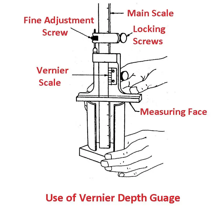
Vernier depth gauge is used for measuring the depth of holes, recesses, and distances from a plane surface to a projection. Here the graduated scale is slide through the base and the vernier scale remains fixed.
Running through the depth gauge body is the main scale the end of which provides the datum surface from which measurements are taken.
The depth gauge is made precisely so that the beam is perpendicular to the base in both directions. The end of the beam is square and flat like the end of the steel rule and the base is flat and true, free from curves or waviness.
It has the advantage of having a large measuring range without having to resort to the use of extension rods as compared to a depth micrometer.
Read also: What are the Different Types of Vernier Caliper?
Parts of Vernier Depth Gauge
Following are the different parts of the vernier depth gauge:
- Main scale
- Vernier scale
- Locking screw
- Fine adjustment screw
- Movable head
- Measuring face
Types of Vernier Depth Gauge
Following are the two different types of depth gauges:
- Analog type
- Digital type
Least Count of Depth Gauge
Following are the least count of depth gauge:
- The least count of the analog depth gauge is 0.02 mm
- The least count of digital type depth gauge is 0.01 mm
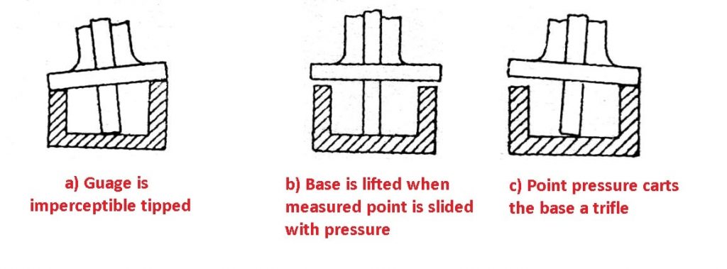
Errors in Using the Depth Gauge
The most common errors are listed below:
- The gauge is imperceptibly tipped.
- The base is liſted when a measured point is slid with pressure.
- Point pressure carts the base a trifle.
The above situations are shown in the figure below:
Steps for Using Depth Gauge
- Thoroughly clean and inspect the attachment.
- Fasten it to the movable jaw.
- Set the depth gauge rod with its end in contact with the surface plate.
- Write down the reading, do not depend on memory.
- Raise the movable jaw to clear the obstruction on the part.
- Place the height gauge in position and lower the movable jaw until the rod of the depth gauge contacts the measured point of the part feature.
- Note the reading. The difference between this reading and the reading in step 4 is the height of the measured point above the reference surface.
Conclusion
That’s it. Thanks for reading. I hope I have covered everything about the “Vernier Depth Gauge” It would be helpful if you could let me know if there was anything I missed or if you have any doubts about anything I wrote.
Please share this article with your friends if you find it interesting.
Want free PDFs direct to your inbox? Then subscribe to our newsletter.
Read Also:
- Vernier Height Gauge: Parts, Specification, Errors, Precaution
- Micrometer Screw Gauge and Types of Micrometers
- Different Types of Manometers: Their Pros and Cons Explained
FAQs
It works on the principle of Vernier scales, where the main scales provide coarse measurements and the vernier scales allow fine adjustments. The user reads the measurement instantly by lining up the vernier scale’s zero point with the main scale.
A Vernier depth gauge is a precise tool that measures the depth of holes, recesses, slots, and steps to within 0.02 mm.
The main drawback is that the caliper only measures linear distance and not volume. Thus, the precision and accuracy are a result of combining at least two different measurements.