Ericsson Cycle With P-v and T-s Diagram
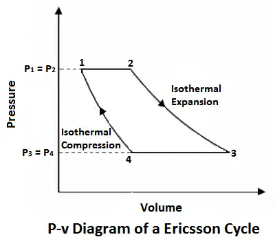
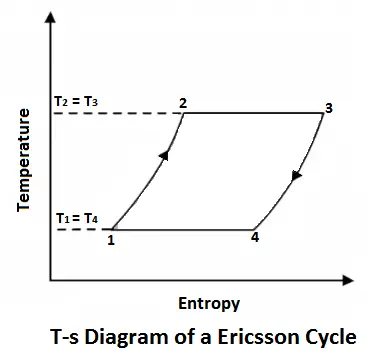
Ericsson Cycle was invented by Ericsson, which consists of two isothermal and two constant pressure processes. It is made thermodynamically reversible by the action of a regenerator. The p-v and T-s diagrams of the Ericsson cycle are shown in the figure. This cycle is used these days in the manufacture of closed-cycle type gas turbines.
J. Ericsson was an American Engineer, who invented this engine in 1840. He used a hot air engine, working on this cycle, for running a ship (known as Ericsson) in 1853.
Read also: Thermodynamic Cycle: Its Classification, Working, Terms Used in Thermodynamics and More.
Now, let us consider the four-stage of the Ericsson cycle. Let the engine contain m kg of air at its original position represented by point 1 on p-v and T-s diagrams. At this point, let p1, T1, and v1 be the pressures, temperature, and volume of the air.
Ericsson Cycle Processes
Following are the four Processes of an Ericsson cycle:
- 1-2 Process (Isothermal expansion or heat addition)
- 2-3 Process (Constant pressure or isobaric heat rejection)
- 3-4 Process (Isothermal compression)
- 4-1 Process (Constant pressure or isobaric heat absorption)
1. Process 1-2 (Isothermal Expansion or Heat Addition)
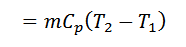
The air is heated at constant pressure from an initial temperature T1 to a temperature T2 represented by the graph 1-2 in fig.
2. Process 2-3 (Constant Pressure or Isobaric Heat Rejection)
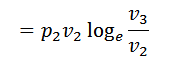
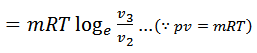
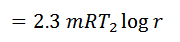
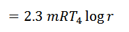
The air is allowed to expand isothermally (i.e., at constant temperature T2=T3) from initial volume v2 to v3 represented by the graph 2-3 in fig. We know that a part of the heat supplied in the first stage is utilized for doing work in isothermal expansion.

3. Process 3-4 (Isothermal Compression)
The air is now cooled at constant pressure from initial temperature T3 to a temperature T4 represented by the graph 3-4 in fig.
4. Process 4-1 (Constant Pressure or Isobaric Heat Absorption)
Finally, the air is compressed isothermally (i.e., at constant temperature T4=T1) from initial volume v3 to v4 represented by the graph 4-1 in fig. We know that some heat is rejected by the air for doing work on the air.


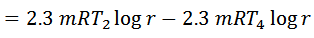
We know from the above, that heat supplied during the process 1-2 is equal to the heat rejected during the process 3-4 (because of T2-T1=T3-T4).
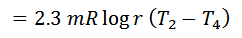
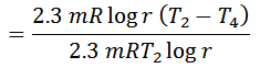
Work done = Heat supplied – Heat rejected
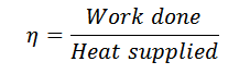
And efficiency,
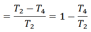
Notes:
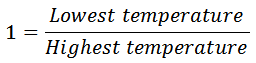
1. The efficiency of the Ericsson cycle is the same as that of Carnot efficiency.
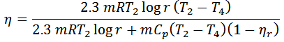
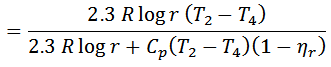
2. If the regenerator efficiency is nr, then heat taken in from the regenerator during process 4-1 will be mCp (T4-T2) (1-nr). In that case.
That’s it, Thanks for reading. If you have any questions about the “Ericsson Cycle and Its Pv – Ts diagram” as in the comments section below. If you found this article helpful share it with your friends.
Want free PDFs direct to your inbox? Then subscribe to our newsletter.
Download PDF of this article:
Read next: