In this post, you’ll learn what is joules cycle its processes and efficiency with P-v and T-s Diagram.
Joules cycle
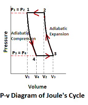
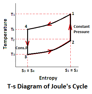
Joules cycle consists of two constant pressure and two adiabatic processes as shown on a p-v and t-s diagram.
Now, let us consider the four stages of the joules cycle. Let the engine cylinder contain m kg of air at its original condition represented by point 1 on p-v and T-s diagram. At this point let p, t, and v be the pressure, temperature and volume of the air.
Read also: Thermodynamic Cycle: Its Classification, Working, Terms Used in Thermodynamics and More.
Joules Cycle Pv Diagram
Joules Cycle Ts Diagram
Joules Cycle Processes
Following are the four Processes of a Joules cycle,
- Constant pressure or isobaric heat addition (Process 1-2)
- Adiabatic expansion (Process 2-3)
- Constant pressure or isobaric heat rejection (Process 3-4)
- Adiabatic compression (Process 4-1)
Read also: Important Terms Used In Thermodynamics
1. Process 1-2 (Constant Pressure or Isobaric Heat Addition)
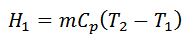
The air is heated at the constant pressure from initial temperature T1 to a temperature T2 represented by the graph 1-2 (a) and (b).
2. Process 2-3 (Adiabatic Expansion)
The air is allowed to expand adiabatically from v2 to v3. The adiabatic expansion represented by the graph 2-3 as shown in the figure (a) and (b). The temperature of the air falls from T2 to T3. In this process, no heat is absorbed or rejected by the air.
3. Process 3-4 (Constant Pressure or Isobaric Heat Rejection)
The air is now cooled at constant pressure from temperature T3 to a temperature T4 represented by 3-4 as shown in figure (a) and (b).
4. Process 4-1 (Adiabatic Compression)
The air is now compressed adiabatically from v4 to v1. The adiabatic compression is represented by the graph 4-1 as shown in the figure (a) and (b). The temperature of the air increases from T4 to T1. Again, no heat is absorbed or rejected by the air.
We see from above, that is no interchange of heat during the two adiabatic processes. The only interchange of heat takes place during constant pressure processes.
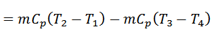
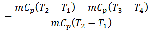
Work done = Heat supplied – Heat rejected
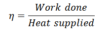
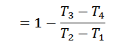
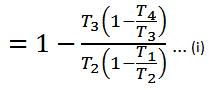
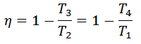
And efficiency,
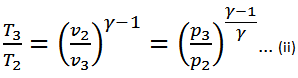
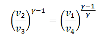
We know that for adiabatic expansion 2-3,
And for adiabatic compression 4-1,
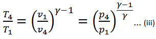

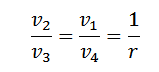
Substituting the values of T4/T3 in equation (i),
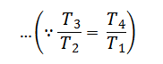
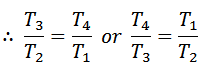
From equation (ii) and (iii) we find that

or
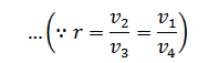
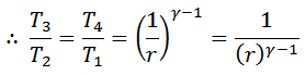
And
Note:
The efficiency of the joules cycle is lower Carnot efficiency. The reason is that all the heat is not taken in at the highest temperature and rejected at the lowest temperature.
The cycle is not thermodynamically reversible, because there is no regenerator to provide a constant temperature during heating and cooling at constant pressure.
The reversed Joules cycle is known as Bell-Coleman cycle and is applied to refrigerators, where the air is used as a refrigerant.
Read Next: Carnot Cycle: Principle Processes, Efficiency with [P-v and T-s Diagram]
That’s it. Thanks for reading. If you have any question on the Joules cycle ask in the comments. If you like this article please share with your friends.
Read also: