In this post, you learn about gas turbine power plants. Their diagram, components, working, advantages, disadvantages, and types of gas turbine power plants.
You can also download the PDF file of this article at the end. So let’s start with the introduction of the gas turbine power plant.
Gas Turbine Power Plant
The gas turbine is the most satisfactory power-developing unit among various means of producing mechanical power due to its exceptional reliability, freedom from vibration, and ability to produce large powers from units of comparatively small size and weight.
The economics of power generation by the gas turbine is proving more attractive in all parts of the world due to its low capital cost and high reliability and flexibility in operation.
Another outstanding feature of gas turbine plants for power generation is the capability of quick starting and the capability of using a wide variety of fuels from natural gas to residual oil or powdered coal.
Now let’s just understand the main components of the gas turbine power plant.
You might like: Different Types of Metals: Their Properties & Applications
Components of Gas Turbine Power Plant
Following are the components of a gas turbine power plant:
- Compressor
- Combustion chamber
- Vertex blading
- Turbine
- Regenerator
- Intercooler
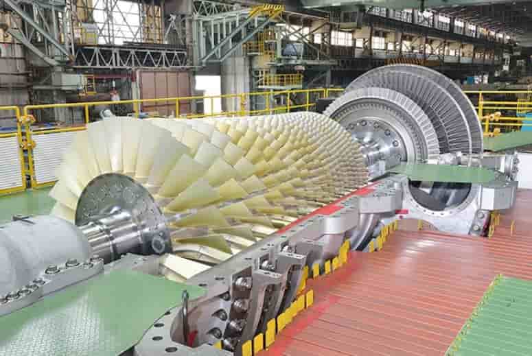
#1 Compressor
The compressor is used to compress the air to higher pressure. The type of compressors that are commonly used is centrifugal and axial flow types. The centrifugal compressor consists of an impeller and a diffuser.
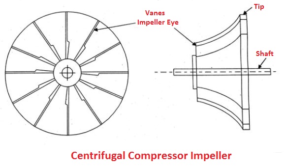
The impeller provides high kinetic energy to the air and the diffuser converts kinetic energy into pressure energy. A centrifugal compressor consists of an impeller with a series of curved radial vanes as shown in the figure. Air is sucked in near the hub, called the impeller eye, and is whirled around at high speed by the vanes on the impeller rotating at high rpm.
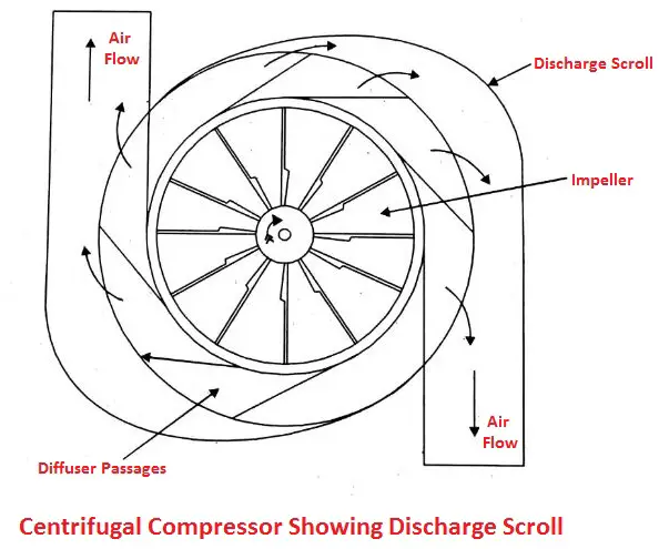
The static pressure of air increases from the eye to the tip of the impeller. The air leaving the impeller tip flows through the diffuser pathway which converts kinetic energy into pressure energy. A pressure ratio of up to 2 to 3 is possible in the single-stage compressor.
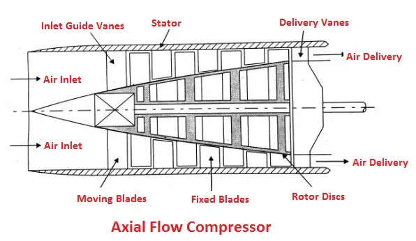
The axial flow compressor contains a series of rotors and stators. The air flows along the axis of the rotor. The kinetic energy is given to the air as it passes through the rotor and part of it is converted into pressure as shown in the figure.
#2 Combustion Chamber
In an open cycle, GT plant combustion may be arranged to take place in one or two large cylinder can-type combustion chambers (CC) with ducting to convey to the turbine.
Combustion is begun by an electric spark and once the fuel starts burning the flame is needed to stabilize.
1. Can-type Combustor With Swirl Flow Flame Stabilizer
A pilot or recirculated inflow to establish stable flame which helps to sustain the zone is created in the main flow to establish stable flame which helps to sustain combustion continuously. The common methods of flame stabilization flow and by the bluff body.
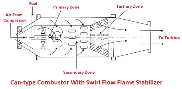
The figure shows a can-type combustor with swirl flow flame stabilization. About 20% of the total air from the compressor is directly fed through a swirler to the burner as primary air, to provide a rich fuel-air mixture. In the primary zone that burns continuously, high temperatures gases are produced.
Air flowing through the swirler produces a vortex motion creating a low-pressure zone along the air of the CC to cause a reversal of flow. About 30% of the total air is supplied through dilution holes in the secondary zone through the annulus around the flame tube to complete the combustion.
Secondary air must be received at the right points in the CC, otherwise, the cold injected air may cool the flame thus reducing the rate of reaction. Secondary air not only helps in completing the combustion process but also helps in cooling the flame tube.
The remaining 50% of the air is mixed with burnt gases in the tertiary zone to cool the gases down to the temperature suited to the turbine blade materials.
2. Can-type Combustion With Bluff-body Flame Stabilizer
The figure shows a can-type combustor with a bluff body stabilizing the flame. The fuel is injected upstream into the airflow and a sheet metal cone and perforated baffle plate ensure the necessary mixing of fuel and air.
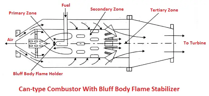
The low-pressure zone created downstream side causes the reversal of flow along the axis of the CC to stabilize the flame. Sufficient turbulence is produced in all three zones of the CC for uniform mixing and good combustion.
#3 Gas Turbines
Like steam turbines, gas turbines are also of the axial flow type as shown in the figure. The primary requirements of turbines are high efficiency, lightweight, reliability in operation, and long working life.
Large work output is obtained per stage with higher blade speeds when the blades are designed to maintain higher stresses. More stages are always preferred in gas turbine power plants because it helps to reduce the stresses in the blades and increases the overall life of the turbine.
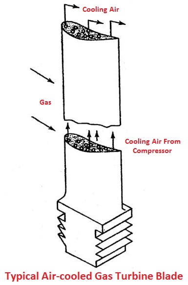
Cooling of gas turbine blades is necessary for a long life as it is subjected to high-temperature gases. Blade angles of gas turbines follow the axial flow compressor blades, where the degree of reaction is not 50%.
It is usually assumed for any stage that the absolute velocity at the inlet to each stage (V2) is equal to the absolute velocity at the exit from the moving blades (ie. V2) and that the same flow velocity Vf is constant throughout the turbine.
The degree of reaction R, as determined for a steam turbine, is true for gas turbines also. It is the ratio of the enthalpy drop in the moving blades to the enthalpy drop in the stage.
You might like: How does a Fuel Injection System Work in a Vehicle?
#4 Vortex Blading
It is the name given to the twisted blades which are designed by using three-dimensional flow equations with a view to decrease fluid flow losses. A radial equilibrium equation can be derived and it can be shown that one set of conditions that satisfies this equation is as follows:
- a) Constant axial velocity along with the blades, i.e. Vf = constant
- b) Constant specific work over the annulus, i.e. Vb∆Vw = constant
- C) Free vortex at the entry to the moving blades, i.e. Vw1r = constant, where r is the blade radius at any point.
Since the specific work output is constant over the annulus, it can be calculated at the mean radius, and multiplied by the mass flow rate it becomes the power for the stage. Since the fluid density varies along with the blade height, the density at the mean radius can be used, so that m = ρmVfA, where A is the blade annular area.
- d) Ductwork: The ductwork consists of ducts between the compressor and the combustion chamber, the combustion chamber to the turbine, and the exhaust duct. The ducts must be sized to minimize the pressure losses, as the loss in pressure directly reduces the capacity of the plant.
#5 Regenerator
The temperature of the gases exiting the turbine is much higher than the temperature of the air being delivered from the compressor.
The heat from exhaust gases can be used to preheat the air delivered by the compressor, reducing the amount of fuel supplied to the combustion chamber. Regenerator is the name for a counter-flow heat exchanger that transfers heat from hot gases to air.
#6 Intercooler
Inter-cooler is only used in gas turbine power plants when the pressure ratios are extremely high and the compression is achieved. The compressed air is cooled using cold water.
The intercooler’s function is to return the temperature of the working fluid between stages to its initial value. The cross-flow intercooler type is typically used to increase efficiency.
Now we are going to understand the working principle of gas turbine power plant.
You might like: Different Types of Evaporators and Their Applications
Working of Gas Turbine Power Plant
A schematic diagram of a gas turbine power plant is shown in the figure. It consists of a compressor, turbine, and combustion chamber.
Atmospheric air is drawn into the compressor and compressed to high pressure. The compressed air is supplied to the combustion chamber where heat is added to the air by burning the fuel and raising its temperature. The hot gas coming out from the combustion chamber is then passed to the turbine where it expands doing mechanical work.
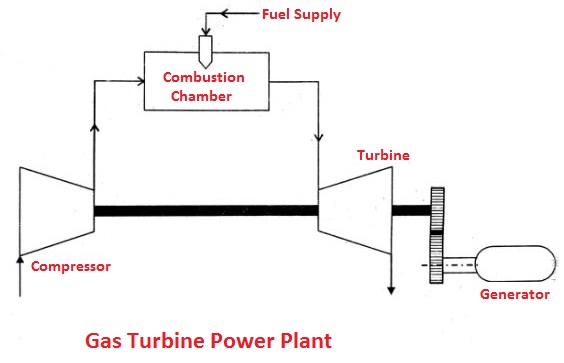
Part of the power developed by the turbine is used to drive the compressor and other auxiliary equipment, and the remaining is used for power generation. The gas coming out of the turbine is exhausted into the atmosphere. This cycle is known as an open-cycle power plant.
If the gas coming out from the turbine is cooled to its original temperature in a cooler and then it is recirculated to the compressor for doing work, such a cycle is known as a closed-cycle power plant.
Read also:
- Wind Power Plant: Importance of Wind Energy, Working, Advantages and applications
- Solar Power Plant: It’s Working and Types of Solar Power Plant
Types of Gas Turbine Power Plant
The gas turbines can be classified into:
- Open cycle gas turbine power plant
- Closed cycle gas turbine power plant
#1 Open Cycle Gas Turbine Power Plant
Simple construction and working of an open cycle gas turbine power plant as shown in the figure. It consists of a compressor, combustion chamber, turbine, and generator. The compressor takes the ambient air and raises its pressure by compression.
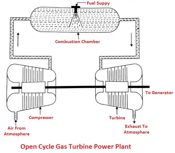
Heat is added to the air in the combustion chamber by burning the fuel and increasing the air temperature. The heated gases coming out of the combustion chamber are then passed to the turbine where it expands doing the mechanical work.
Part of the generated power by the turbine is utilized in driving the compressor and other accessories and the remaining is used for power generation. Since ambient air enters the compressor and gases coming out of the turbine are exhausted into the atmosphere, the working medium must be replaced continuously.
This type of cycle is known as an open cycle gas turbine power plant and it is mainly used in the majority of gas turbine power plants as it has many inherent advantages.
Advantages of Open Cycle Gas Turbine Power Plant
The following are the advantages of an open-cycle gas turbine power plant:
- Once the turbine started, it will accelerate from a cold start to a full load without warm-up time.
- Low weight and size.
- It occupies relatively less space.
- Almost any hydrocarbon fuel from high-octane gasoline to heavy diesel oils can be used in the combustion chamber.
- It does not require cooling water except for those having an intercooler.
- Through auxiliary refinements, we can improve thermal efficiency and give the most economic overall cost for the plant load factors.
Read Also: What are the different types of furnaces? Their Working & Uses
#2 Closed Cycle Gas Turbine Power Plant
Simple construction and working of a closed cycle gas turbine power plant as shown in the figure. It consists of a compressor, combustion chamber, turbine, generator, and precooler. The working fluid may be air or any other suitable gas coming out from the compressor with high pressure and is heated in a heater by an external source at constant pressure.
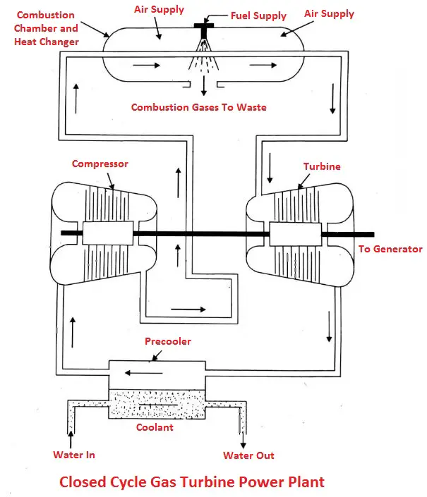
The high temperature and high-pressure air coming out from the combustion chamber are passed through the gas turbine where it expands doing the mechanical work. The fluid coming out from the turbine is cooled to its original temperature in the cooler using an external cooling source before passing to the compressor.
The working fluid is continuously used in the system without its change in phase and the required heat is given to the working fluid in the heat exchanger.
Advantages of Closed Gas Turbine Power Plant
The following are the advantages of a closed gas turbine:
- No contamination.
- Higher thermal efficiency.
- Improved load part efficiency.
- No loss of working medium.
- Expensive fuel
- Reduced size.
- Improved heat transmission.
- Less fluid friction.
- Greater output.
Disadvantages of Closed Gas Turbine Power Plant
The following are the disadvantages of closed gas turbines:
- Complicated in design.
- The high initial cost of the plant.
- It requires a high quantity of cooling water.
- Poor response to the load variations.
- It requires a very big heat exchanger.
Don’t Miss: What is Steam Condenser? Their Advantages and Disadvantages
Advantages of Gas Turbine Power Plant
The following are the advantages of a gas turbine power plant:
- The work developed per kg of air is large compared to the diesel plant.
- Less space is required.
- Less vibration due to perfect balancing.
- Low capital cost.
- Higher mechanical efficiency.
- The higher the speed of the turbine.
- Low installation and maintenance costs.
- Simple ignition and lubrication systems.
- Poor-quality fuels can be used.
- Better torque characteristics of the plant.
- No ash handling problem.
Disadvantages of Gas Turbine Power Plant
- Poor part-load efficiency.
- Special cooling methods are required for cooling turbine blades.
- Short life.
- Special metals and alloys are required for components.
Applications of Gas Turbine Power Plant
Gas turbine plants are used for the following purposes:
#1 Power Generation
To generate electricity, gas turbines are frequently used. Gas turbines are divided into three categories based on how they use power:
1. Small Sized Gas Turbine
It produces less energy than 2 MW. The centrifugal compressor in the turbine is powered by a radial inward flow turbine.
2. Medium Sized Gas Turbine
This turbine generator has a power rating of between 5 MW and 50 MW. It is made up of axial-flow compressors and turbines.
3. Large-Sized Gas Turbine
These turbines produce more than 50 MW of power. They are run at a very high temperature of generally 13–15 °C and a pressure ratio of 35:1. 2.
#2 Aviation
The air compressors in turbo-jet and turbo-propeller engines are driven by gas turbines, which are widely used in the aircraft industry. The operating temperature range for these engines is between 800°C and 1000°C.
#3 Supercharger
Additionally, the compressed air produced by the gas turbines can be used in superchargers. Both the heavy-duty diesel engines and the petrol engines used in aircraft are equipped with these superchargers.
#4 Marine Engines
Since gas turbines don’t need water storage tanks or distillation facilities, they can also be used in marine engines.
#5 Railway Engines
Gas turbines are primarily used to power the air compressor in railway engines. Other uses for gas turbines include powering turbo pumps, rotary compressors, high-speed race cars, and hovercrafts.
Advantages of Gas Turbine Power Plant with Nuclear Power Plant
The following are the advantages of a gas turbine power plant with a nuclear power plant:
- Low weight and size: i.e. wt of the plant per kW output is low.
- Any hydrocarbon fuel from high-octane gasoline to heavy diesel oil can be used efficiently.
- Easy start-up and shutdown.
- Very low cooling water is required.
- No waste disposal problem.
- Environmental friendly.
- Low operational cost.
- Low installation cost.
- It can be located at the load center. Therefore, the transmission loss is very less.
- Scope for co-generation i.e. used to produce process heat for various uses.
- Low risk in operation.
- Low cost of fuel.
- Less floor space is required for its installation.
Conclusion
That is it, thanks for reading. If you have any questions about the types of “Gas Turbine Power Plant” leave a comment. If you like the article share it with your friends.
Want free PDFs in your inbox? Then subscribe to our newsletter.
Download PDF of this article:
Read Next:
- What are the Importance of a Hydro Power Plant?
- Understand The Different Types of Condensers
- How does an Air Conditioning System work?
External Links:
PLEASE CANI GET THE PDF FOR THIS
The PDF file has been sent to your inbox.
Thanks so much for this article on power plant. So much appreciate it.
Like to be receiving more from you.
Glad you liked it.
Thanks, your write up is really insightful nice and helpful content. Thanks for sharing a helpful article with us.
You’re welcome 🙂