In this article, you’ll learn about what is D.C. generator and how it works with its working principle, parts, construction and types of DC generators, application and more
DC Generator and Types
An electrical DC generator is a machine that turns mechanical energy into electrical energy. Or in other words, it is a machine that converts mechanical energy into a direct current.
Working Principle of DC Generator
The energy conversion takes place on the principle of the production of the dynamically induced emf i.e, whenever conduct cuts magnetic flux, dynamically emf is induced in it according to Faraday’s laws of electromagnetic induction. This induced emf provides a flow of current in a conductor if the circuit is closed.
Read Also: 12 Fundamental Parts of DC Generator & Its Functions [Complete Guide]
Construction of D.C. Generator
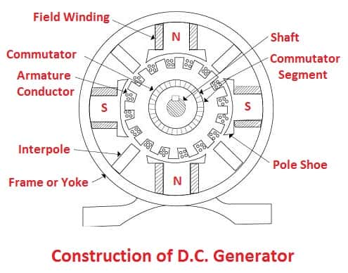
The above figure represents the practical generator which consists of
- Magnetic frame or yoke
- Pole-cores and Pole-shoes
- Pole-coils and Field coils
- Armature windings or conductors
- Commutator
- Brushes and bearings.
The DC generator consists of a single-turn rectangular copper coil ABCD rotating about its own axis placed magnetic field provided by electromagnets and a permanent magnet shown in the figure.


The ends of the coil are connected to the central shaft consisting of two slip rings that are insulated from each other. The two collecting brushes are pressed against slip rings, which are used to collect the current induced in the coil and to convey it to external load resistance ‘R’.
Read also: DC Motor: Types, Parts, Working Principle, Applications
Working of D.C. Generator
When the plane of the coil (ABCD) is at right angles to the line of flux i.e., when it is in position 1, then the flux linked is maximum, but the rate of change of flux linkages is minimum, the sides of coil AB and CD do not cut the flux, but they move parallel to them. Hence e.m.f induced is zero, as shown in the figure.

Now the coil starts to rotate in a clockwise direction, which changes the rate of flux linkages hence induced emf starts to increase till the coil is at position 3 (i.e., 0 = 90°), i.e., at this position, flux linked is minimum, but the rate of change of flux linkages is maximum hence e.m.f induced is maximum as shown in fig (b).

When the coil starts rotating from 90° to 180°, the flux linked with the coil starts to increase, so the rate of change of flux linkages decreases. Hence the emf-induced decreases till the coil reaches position 5. At this position, emf becomes zero. Thus from position 1 to 5. the first half revaluation of the coil is completed and the direction of current flow is ABMLCD (fig. 1).
During the next half revaluation, i.e., from 180° to 360°, the variations in emf induction remain the same as that of the above revaluation. In this half revaluation, emf’s maximum in the coil position 7 and minimum in position 1. But the direction of current flow is DCLMBA fig (a),

Which is just reverse to that of the first half. Thus for both half revaluation current direction is opposite i.e., it generates an alternating current. To make the flow of current unidirectional in the external circuit, the split-rings fig. (b) are used

Due to the split-rings, the current flow is unidirectional i.e., during first half revaluation brush no. 1 is in constant with segment ‘a’ and it acts as (+)ve end of supply and ‘b’ acts (-) ve end similarly during second half revaluation, the direction of current is reversed and the segments ‘a’ and ‘b’ have reversed but brush no. 1 comes in contact with them which is (+)ve i.e., segment ‘b’.

Hence current in the load resistance flows from M to L only. Thus current becomes unidirectional as shown in the figure (5).

Read Also: 14 Necessary Parts of Transformer & Its Functions [Names & Pictures]
Types of DC Generators
Following are the main three types of DC generators:
- Permanent magnet DC generator
- Separately excited generator
- Self-excited Generator
Read also: A.C Motors: Types, Working, Construction, Applications.
#1 Permanent Magnet DC Generator
A permanent magnet DC generator basically converts mechanical energy into electrical energy. These usually have a double permanent magnet and a double winding structure. It works on the principle of electromagnetic induction, in which the electric potential is induced by cutting the magnetic line of force to convert the energy.
It mainly consists of two working parts, which are the stator and rotor. The stator has an armature core, three-phase winding with uniform discharge, base, and end cover, etc. Whereas rotor is a hidden pole type with excitation winding, iron core, shaft, retaining ring, central ring, etc.
The exciting winding of the rotor is linked to a DC current supply, which produces a magnetic field close to the rotor’s magnetic field. As the rotor rotates, the rotor’s magnetic field rotates with each rotation for one cycle.
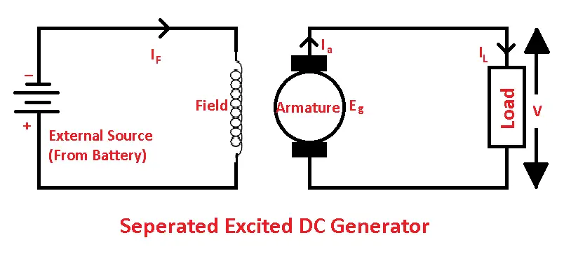
#2 Separately Excited DC Generator
In the separately excited type, the field winding is supplied with an autonomous external DC source (battery). Separately excited DC generators are not commonly used. This means that they are rarely used.
In this, the magnitude of the voltage depends on the speed of rotation of the armature and the field current. This means the greater the speed and field current, the greater the voltage generated.
- Ia = Armature current
- IL = Load current
- V = Terminal voltage
- Eg = Produced electromagnetic force
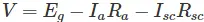
Armature’s voltage drop = Ia × Ra (R/sub>a is the armature resistance)
Let,
Then,

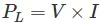
Power produced is equivalent to
The external load receives power equal to
Read Also: What Are The Different Types of Transformers and Their Working?
#3 Self-excited DC Generator
In the self-excited type, the field coil is reinforced by the field generated by the generator. The generation of the first electromotive force will arise due to the excellent magnetism within the field pole.
The electromotive force produced will cause a fraction of the current to be supplied to the field coil, so this will increase field flux as well as electromotive force generation. Furthermore, these types of DC generators can be classified into three types such as series-wound, shunt-wound, and compound wound.
The self-excited generator is further classified according to their arrangement of file cols.
- Series Wound Generators
- Shunt Wound Generators
- Compound Wound Generators
Read Also: 25 Different Types of Electrician Tools and Their Working [Full Guide]
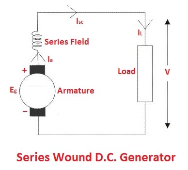
1. Series Wound Self-excited Generators
In this type of generator, field windings are coupled in series with armature conductors. The entire current flows through the coils as well as the load. As the series field winding flows full load current, it is designed with relatively few turns of thick wire. Therefore the electric resistance of series field winding is very low (about 0.5Ω).
In this,
- Rsc = Series winding resistance
- Isc = Current flowing through the series field
- Ra = Armature resistance
- Ia = Armature current
- IL = Load current
- V = Terminal voltage
- Eg = Generated EMF
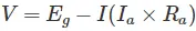
Then,
The voltage across the load is equivalent to
Power produced is equivalent to,

The load is supplied with power equal to,

Read Also: 9 Different Types of Batteries and Their Applications [You Must Know]
2. Shunt Wound Excited Generator
These types of DC generators have field windings that are coupled in parallel with the armature conductor, as shown in the figure. In shunt-wound generators, the voltage across the field is the same as the voltage across the terminal.
In this,
- Rsh = Resistance of the shunt winding
- Ish = Current flowing through the shunt field
- Ra = Armature resistance
- Ia = Armature current
- IL = Load current
- V = Terminal voltage
- Eg = Generated EMF
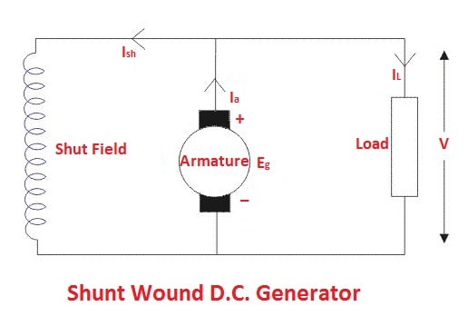
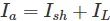
The armature current Ia is divided into the load current IL and the shunt field current Ish.
Therefore,

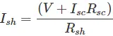
When IL is maximum the effective power across the load will be maximum. Therefore, it is necessary to keep the shunt field as small as possible. For this purpose, the resistance of shunt field winding is generally kept high (100 Ω) and a large number of windings are used for the desired EMF.
A shunt field current equals,

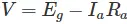
Voltage across the load is equivalent to
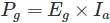
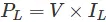
Power produced is equivalent to,
The load is supplied with power equal to,

Read Also: What Are The Different Types of Circuit Breakers? Working & Applications
3. Compound Wound Excited Generator
In series-wound generators, the output voltage is directly proportional to the load current. In a shunt-wound generator, the output voltage is inversely proportional to the load current. The combination of these two types of generators can overcome the limitations of both. This combination of windings is termed a compound wound DC generator.
The compound wound generator has both series field winding and shunt field winding. One winding is arranged in series with the armature, and the other is arranged parallel to the armature.
These types of DC generators are further classified into two types.
- Short Shunt Compound Wound DC Generator
- Long Shunt Compound Wound DC Generator
1. Short Shunt Compound Self-excited Generators
Short shunt compound wound DC generators shown in the above figure. These are generators where only the shunt field winding is parallel to the armature winding.
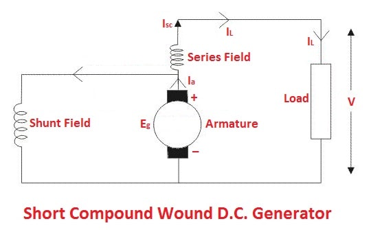
The series field current is equivalent to,

Shunt field current equals,
The equivalent armature current is,
The voltage across the load equals,
The power produced is equivalent to,

The load is supplied with power equal to,
Read Also: What is Electric Motor? Its Types, Working & Applications [Explained]
2. Long Compound Self-excited Generators
These are the generators where the shunt field winding is parallel to both the series field and armature windings, as shown in the figure.
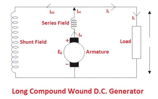
The shunt field current is similar to,

Armature current (Ia), is equal to series field current
Voltage across the load is equivalent to

Power produced is equivalent to,

The load is supplied with power equal to,

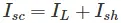
In a compound wound generator, the shunt field is more robust than the series field. When the series field supports the shunt field, the generator is known as a commutatively compound wound.
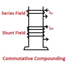
If the series field opposes the shunt field, the generator is known as a differentially compound wound.
Read Also: Different Types of Insulators Used In Power Transmission Lines
Applications of D.C. Generators
- Separately excited D.C. Generators: They are used:
- In mine hoists and steel mill drives.
- For papermaking machines.
- In diesel-electric locomotives etc.
- Series wound D.C. Generators
- Used in series are lighting.
- Used in series boosters.
- Shunt-wound D.C. Generators:
- With field regulators, these are used for light and power supply purposes.
- Used for charging batteries they can be made to give constant output voltage.
- Cumulative compound wound D.C. Generators:
- Used for lighting and power services.
- Differential compound wound D.C. Generators:
- It is used as an arc welding generator, it is a constant current generator.
That’s it, thanks for reading. I hope you find this article helpful then please share this with your friends. If you have any questions about “types of dc generators” ask in the comments I’ll respond to you.
Want free PDFs direct to your inbox? Then subscribe to our newsletter.
Download PDF of this article:
Read Next:
- Capacitors: Types, Definition, Specifications and Application of Capacitor
- What is Resistance Welding? Types, Working, & Applications
- Different Types of DC Motors: Parts, Working, Application [Complete Guide]
- 12 Different Types of Inductors and Their Applications [PDF]
- Electric Circuit: Types of Circuits with [Diagrams & Pictures]
sent me this course in pdf
The PDF file has been sent to your inbox.
sent me this one please
The PDF file has been sent to your inbox.
it is very supportive and amazing explanation . can you send PDF ?
Thanks for reading. The PDF file has been sent to your inbox.
Hi there. How do I join to share my knowledge as well? My experience is in heavy earth movers specialising in Caterpillar brands.
Thanks
Hi, you can join our Facebook group @theengineerspost(PDF) and share your things there.
hola buena explicacion me podrias vidrar tu pdf
The PDF file has been sent to your inbox.