Lathe machine formula for cutting speed, feed, and depth of cut
A lathe machine is a machine that holds the workpiece on a chuck and tool on a toolpost, the lathe machine rotates the workpiece about an axis to perform different operations such as turning, facing, chamfering, thread cutting, knurling, drilling, and more with tools that are applied to the workpiece to design an object with symmetry about that axis.
The following are the lathe machine formula commonly used to calculate in turning operations:
- Cutting speed
- Feed
- Depth of cut
- Machining time
1. Cutting Speed
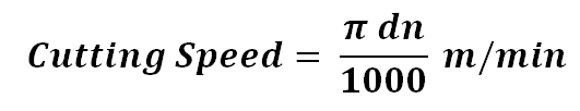
The cutting speed (v) of a tool is the speed at which the metal is removed by the tool from the workpiece. In a lathe, it is the peripherical speed of the work past the cutting tool expressed in meters per minute.
Where,
- d – is the diameter of the work in mm.
- n – is the r.p.m of the work.

In the British system, cutting speed is expressed in feet per minute and diameter of the work in inches.
Where,
- d – is the diameter of the work in inches, and
- n – is the r.p.m of the work.
The cutting speed, direction of feed and depth of cut to be given to a workpiece are shown in the figure below.
Example 1)
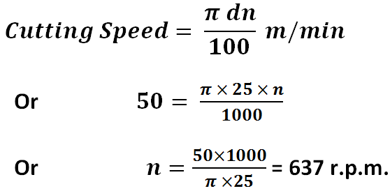
A steel shaft of 25mm diameter is turned at a cutting speed of 50 metres per minute. Find the r.p.m. of the shaft.
In practice, when the calculated speed is not available in the machine the next lower value is selected.
2. Feed
The feeds of the cutting tool in lathe work are the distance the tool advances for each revolution of the work. A feed is expressed in millimetres per revolution.
In the British system, it is expressed in inches per revolution.
Increased feed reduces cutting time. But increased feed greatly reduces the tool life. The feed depends on factors such as size, shape, strength and method of holding the component, the tool shape and it’s setting as regards overhang, the rigidity of the machine, depth of cut, power available, etc. rougher feeds are applied for roughing and finer feeds for finishing cuts.
3. Depth of Cut
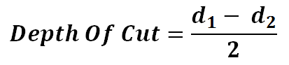
The depth of cut (t) is the perpendicular distance measured from the machined surface to the uncut surface of the workpiece. In a lathe machine, the depth of cut is shown as follows:
Where,
- d1 – diameter of the workpiece surface before machining.
- d2 – diameter of the machined surface.
Another factor remaining fixed, the depth of cut changes inversely as the cutting speed. For general purpose, the ratio of the depth of cut to the feed varies from 10:1
4. Machine Time
The machining time in the lathe work can be calculated for a particular operation if the speed of the job, feed and length of the job is known.
If “s” is the feed of the job per revolution expressed in mm per revolution and “l” the length of the job in mm, then a number of revolutions of the job required for a complete cut will be: l/s.
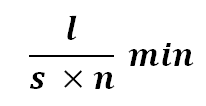
Therefore, the time is taken for a complete cut = l / s X n min.
If the r.p.m. of the work is n, the time is taken to revolve the job through l/s number of revolutions for a complete cut will be:
Example 2)
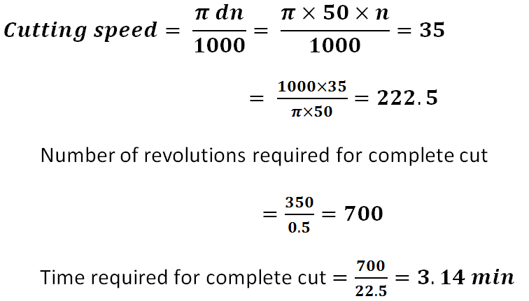
Find the time required for one full cut on a workpiece of 350mm long and 50mm in diameter. The cutting speed is 35 metres per minute and the feed is 0.5mm per revolution.
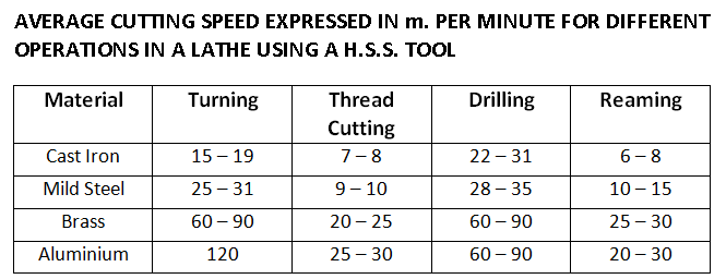
Average cutting speed expressed in meter per minute for different operations in a lathe using an H.S.S. tool
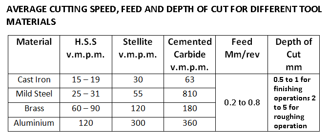
Average cutting speed, feed and depth of cut for different tool materials:
Cutting Tool Signature
The signature is a sequence of numbers listing the various angles, in degrees, and the size of the nose radius. This numerical method of identification has been standardized by the American Standards Association.
The seven elements that comprise the signature of a single-point cutting tool are always started in the following order:
- Back Rack Angle
- Side Rake Angle
- End Relief Angle
- End Cutting Edge Angle
- Side Cutting Edge Angle
- Nose Radius
Thus a tool with shaped specified as 8-14-6-6-6-15-4 has 8° back rake, 14° side rack, 6° end or side relief, 6° end cutting edge and 15°side cutting edge angles, and 4mm nose radius.
Plan Approach Angle
In cutting tool terminology used in the U.S.S.R., there is another angle called plan approach angle this is the complementary angle to the side cutting edge angle used in cutting tool terminology in India, Great Britain and the U.S.A.
This is the angle between the projection of the side cutting edge on the basic plane and the direction of feed. It is sometimes called the entering angle.
Download the PDF file of this article:
That’s it.
Thanks for reading the article on lathe machine formula and calculation. If you have any problems or questions regarding this topic tell us in the comment section below.
Read more about lathe machine:
please enable the download icon below your work
I will soon update the article with new PDF file.
Thank you for the illustrative and concise article, greatly appreciated!
You’re most welcome.
VERY INTERESTING AND EDUCATING.
Thanks
Plz enable the download in PDF version of this
Hi there, Thanks for reading, I just sent you the PDF file of this article to your email address.
Can you send the pdf to me too
Sure, I have sent you the PDF file to your inbox.
Very good learning article it’s really helpful
Thank you 🙂
I wa t all mechanical engineering turning and milling operation formulas
Sure, I’ll upload it soon 🙂
Its an excellent material thanks a lot
You’re Welcome 🙂
it’s very good
Thanks