Hello readers! In this post, we’ll discuss the different types of lathe cutting tools and their applications using illustrations.
So let’s start with what are lathe cutting tools?
Lathe Cutting Tools
A lathe is a machine that rotates the workpiece about an axis of rotation to perform various operations such as turning, undercutting, knurling, drilling, facing, boring, and cutting, with lathe cutting tools that are applied to the workpiece to create an object with symmetry about that axis.
The tool used is a single-point cutting tool for general-purpose work, but multi point cutting tools may be used for special operations. Watch the video below to get a better understanding of lathe machine operation.
In lathe machine work, different operations require different types of lathe cutting tools, according to the process of using the lathe cutting tools.
Now, let’s discuss the different types of lathe cutting tools.
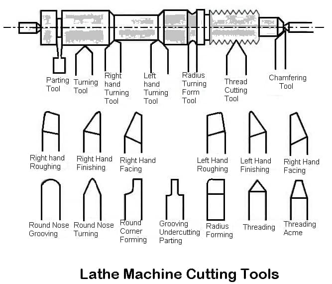
Types of Lathe Cutting Tools
Following are the types of lathe cutting tools used in lathe machine:
- Turning tool.
- Chamfering tool.
- Thread cutting tool.
- Internal thread cutting tool.
- Facing tool.
- Grooving tool.
- Forming tool.
- Boring tool.
- Parting-off tool.
- Counterboring tool
- Undercutting tool
- According to the method of applying feed
- Right-hand tool
- Left-hand tool
- Round Nose
Lathe Cutting Tools Based on the Material Used
Tools used on a lathe can be made from a wide variety of materials, each with special qualities. Each lathe-cutting tool thus displays characteristics based on the mechanical properties of the material. According to the type of material, the typical lathe cutting tools are listed below.
#1 High-Speed Steel (HSS)
High-speed steel is made of elements such as tungsten, carbon, vanadium, and chromium. This material is used to create cutting tools that are extremely strong, wear- and heat-resistant, and extremely hard. They also have a high speed that is appropriate for rough and semi-finish machining.
#2 Diamond
Diamond-based lathe-cutting tools are extremely difficult to use. They are appropriate for working with all materials. However, they are expensive, just like carbide tools, which restricts their industrial use.
#3 Carbide
The cutting tools made of carbide are brittle and hard. As a result, they work with almost all materials. Even so, their high cost limits their use for the production of parts.
#4 Cubic Boron Nitride
The next hardest material is cubic boron nitride. These tools are strong, abrasion resistant, and ideal for workpiece cast iron that requires rough machining and intermittent cutting.
Lathe Cutting Tools Based on Operations
According to the machining operation, lathe cutting tools are also divided into categories. The standard tools used in each lathing operation are listed below.
#1 Turning Tool
There are mainly two classes of turning tools:
- Rough turning tool.
- Finish turning tool.
1.1 Rough Turning Tool

The main function of a rough turning tool is to remove the maximum amount of metal in the minimum time that the tool, work, and machine will permit. The cutting angle is so ground that it can withstand maximum cutting pressure.
1.2 Finish Turning Tool

The turning tool is used to remove a very small amount of metal. A tool angle is so ground that it can produce a very smooth and accurate surface.
#2 Chamfering Tool
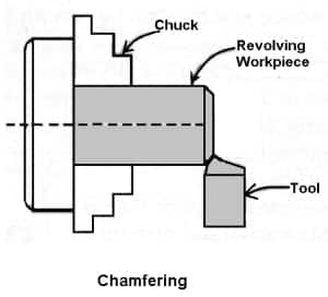
Straight turning tools are also used as a chamfering tool when the cutting edges are set at an angle of the chamfer. Where a large number of chamfer works are to be performed a special chamfering tool with its side cutting edge angle ground to the angle of the chamfer is used.
#3 Shoulder Turning Tool
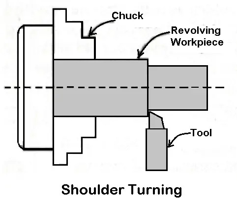
A square shoulder is turned by a knife-edge turning tool or facing tool. A beveled shoulder may be turned by a straight turning tool having a side cutting edge angle and zero nose radius. A filleted shoulder is turned by a straight-turning tool with a nose radius corresponding to the fillet radius of the work.
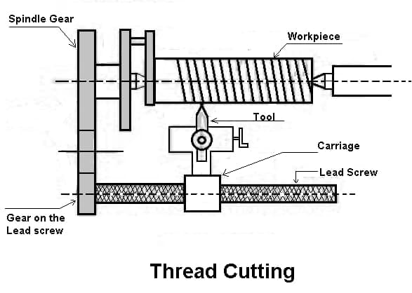
#4 Thread Cutting Tool
4.1 External Thread Cutting Tool
Metric, B.S.W, or American “V” threads are formed by a single-point thread-cutting tool. Its cutting edges are sharpened to the shape and size of the thread to be cut.
The shape of the tool is determined by the included angle at the nose of the tool which should correspond to the angle of the thread. It may be 60° for metric threads or 55° for B.S.W threads.
he included the angle at the nose of the tool which should correspond to the angle of the thread. It may be 60° for metric threads or 55° for B.S.W threads.
The size or cross-section of the cutting edges of the tool depends upon the pitch of the thread. The below figure illustrates an H.S.S. thread-cutting tool.
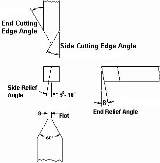
So for machining different screw threads having different pitches separate tools are used to produce accurate threads. The nose of the tool is pointed, flat, or rounded according to the shape of the root of the thread.
A thread tool gauge is used to check the shape and size of the tool after it has been ground.
4.1.1 Tool for cutting square threads
The side clearance of the tool for cutting square thread is of prime importance in order to prevent the tool from interfering with or rubbing against the vertical flank of the thread.

As a rule, the forward side clearance angle is determined by adding 5° to the helix angle of the thread, and trailing side clearance is obtained by subtracting 5° from the helix angle, if ø is the forward side clearance angle and θ is the trailing side clearance angle, then from the formula:
The width of the cutting edge should be equal to half the pitch of the thread.
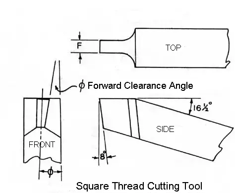
Small clearance angle of 1° to 2° are provided at the side of the tool to prevent the surface from ribbing with the work.
4.2 Internal Thread Cutting Tool
The cutting edge of the tool is exactly similar to an external thread cutting tool but the front clearance angle is sufficiently increased as in a boring tool.
The tool is a forged type orbit type and is held on a boring bar. The point of the tool must be set square with the work.
Read also: 22 Different Types of Operations used in Lathe Machine
#5 Facing Tool
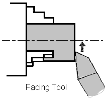
A facing tool removes metal by its side cutting edges. So no top rake is necessary in a facing tool. The figure shows H.S.S. facing tool intended for finishing operation.
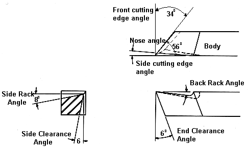
The tool has a 2° side cutting edge angle and a 34° end cutting edge angle that can be accommodated in the space between the end of the work and 60° dead center leaving a clearance of 2° on both sides.
The standard shank section is 20Χ20, 25Χ25, 32Χ32, 40Χ40, and 50Χ55 all expressed in mm. The length of the tool is 125, 140,170, 200, and 240 mm and the nose radius varies from 0.5 to 1.6 mm.
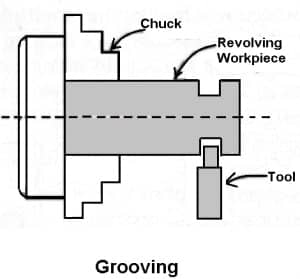
#6 Grooving Tool
The grooving tool is similar to a parting-off tool illustrated in the figure. The cutting edges are made square, rounded, or “V” shape according to the shape of the groove to be cut.
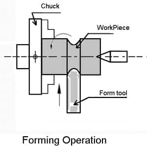
#7 Forming Tool
Turning curved profiles may be affected by using
- Ordinary lathe tools,
- Flat forming tools,
- Circular forming tools.
An ordinary lathe turning tool may serve the purpose where a copying attachment is used to reproduce the form of a template. Flat-forming tools are made of two types:
- Simple forming tools
- Flat dovetail forming tools.
1. Simple forming tools
These tools have their cutting edges ground to the shape of the groove, undercut, or thread to be cut.
Flat dovetail-forming tools have a wider cutting edge corresponding to the shape desired. The tail end of the tool is fitted in a special tool holder. No front rake is provided but sufficient front clearance angle is given and it ranges from 10° to 15°.
Regrinding is always done on the top face of the tool which does not alter the form of the tool.
2. Circular Form Tools
These tools are preferred in production work as a very long cutting surface can be used resulting in longer tool life.
The centre of the tool is set slightly above the centre line of the work to provide an effective front clearance angle on the tool. The tool will rub against the work if the centres are of the same height.
The tool centre is usually higher than the centre line of the lathe by 1/20 to 1/10 of the tool diameter. This height is termed ‘offset’. Regrinding is done by grinding the flat only.
#8 Boring Tool
A boring tool is similar to a left-hand external turning tool so far its cutting edge is concerned.
The tool may be a bit type inserted in a boring bar or holder, or forged type having a tool shank. The figure shows an H.S.S. tool bit inserted in a boring bar.
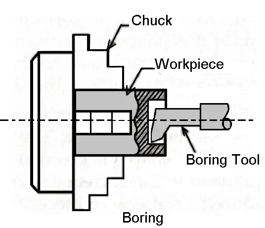
A boring bar is made of mild steel with slots or holes cut into it to accommodate the tool bit which is locked by an Allen screw. The amount of projection of the cutting edge of the tool from the center of the bar determines the finished hole diameter of the work.
The bit is generally inserted at right angles to the center line of the bar for boring a continuous hole passing from one end to the other end.
8.1 Different Design of The Boring Tool
The bit is set at a single to the axis projecting beyond the end of the bar to bore a blind hole.
- A tool bit having two cutting edges at its two ends is used for quick machining.
- A wide double-bladed cutter is inserted in the boring bar to finish the boring operation.
- Two or more bits may be inserted in a boring bar for different diameters in one setting.
8.2 Boring Bars:
- Boring bars are held in the tailstock for boring small holes ranging from 12 to 100 mm.
- For boring larger hole diameters, boring bars are gripped by two clamp blocks and held in the tool post.
- For precision boring or boring in size work that is supported on cross-slide, the bar is supported on centers and is made to revolve.
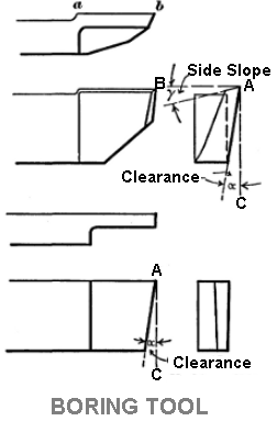
8.3 Clearance for Boring Tool
- In a boring tool, the tool’s cutting edge must have sufficient front clearance to clear the work.
- To strengthen the tool point double clearance, primary and secondary, is provided.
- The smaller the hole diameter the larger should be the front clearance.
- A larger clearance angle necessitates a reduction in the rake angle in a boring tool.
- The nose of the tool is straight or round according to the type of finish desired.
#9 Counterboring Tool

The counterboring operation can be performed by an ordinary boring tool. The tool cutting edge is so ground that it can leave a shoulder after turning. A counterbore having multiple cutting edges is commonly used.
#10 Undercutting Tool
Undercutting or grooving tool has a point and form of the cutting edge exactly similar to the form of the required groove.
Clearance angle is given at all the sides of the tool. For the recessing groove cutting edge, the longitudinal feed is employed. The front clearance angle depends upon the bore of the work.
#11 Parting-off Tool
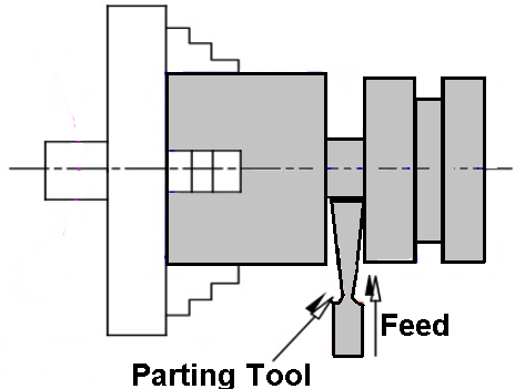
A parting off tool is normally forged and used as bits for cemented carbide tipped tools. Parting off tool is made as narrow as possible to remove the minimum of metal.
The width of the cutting edge range from 3 to 12 mm only. The length of the cutting tool which inserts into the work should be slightly longer than the radius of the bar stock being machined.
As the tool penetrates deep into the work, clearance is provided all around the tool cutting edge to prevent it from rubbing against the work surface.
As the tool is purely ended cutting it has no side rake slight back rake is provided on the tool to promote an easy flow of the ships.
Read also: Cutting speed, Feed, Depth of cut & Machining time in lathe machine
Lathe Cutting Tools Based on Applying Feed
- Right-hand tool
- Left-hand tool
- Round Nose
#1 Right-Hand Tool
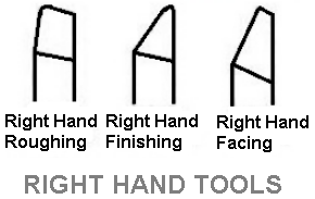
A right-hand tool is shown in the figure. Is that which is fed from lathe bed, i.e. from the tailstock to the headstock end when operations like turning, thread cutting, etc are performed.
A right-hand tool is formed on its left-hand end when viewed from the top with its nose pointing away from the operator.
#2 Left-Hand Tool
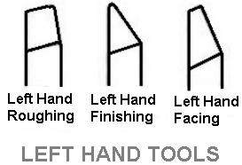
The left-hand tool is shown in the figure. Is that which is fed from the Left to the right-hand end of the lathe bed, i.e. from the headstock to the tailstock end.
The left-hand tool is used for left-hand thread cutting operation or turning operation which leaves a shoulder on the right-hand end of the workpiece.
A left-hand tool has its cutting edge formed on its right-hand end when viewed from the top with its nose pointing away from the operator. A left-hand tool may also be used for facing operation.
#3 Round Nose Tool

A round nose turning tool sown in the figure. Maybe fed from left to the right or from right to the left-hand end of the lathe bed away. For this reason, they have no back rake and side rake.
In some cases, a small back rake is provided on the tool. A round nose turning tool is usually used for finish turning operation.
Lathe Cutting Tools Based on Structure
Based on their structural design, there are three main categories of lathe cutting tools. As follows:
#1 Single Body Tools
These tools have a specific shape, size, and geometry and are made from a single piece of material. Due to their speed and strength, they are the most popular lathe machine tools.
#2 Welding Lathe Cutting Tools
These tools have a rod and a head made of various materials that are welded together. The flank is typically made of strong, long-lasting materials like carbide, whereas the body can be made of various metals. They provide less cutting force than single-body tools because of the differences in the materials.
#3 Clamp Lathe Cutting Tools
The material composition of these cutting tools is similar to that of welding tools. The clamp lathe tool is, however, formed by placing an insert (i.e., a cutting tool) on a handle bar instead of a welding tool.
Clamp lathe cutting tools are typically flexible and replaceable. As a result, the type of inserts affects their qualities, such as strength and durability.
Read also: 7 Types Of Lathe Machine Chucks
That’s it, thanks for reading. If you have any questions on “lathe cutting tools” ask in the comment below. If you found this article helpful please share with your friends.
Now you can download the PDF file of this post.
Subscribe to our newsletter to get notifications:
Read Also:
A useful site .Thank you.
You’re welcome.
HI.
I’ve just been given an Axminster mini lathe and this information is extremely useful.
Thanks very much.
You’re welcome. Keep visiting.
Skimming info I really liked what you had posted and wud Iike to get on any subscription list you may have so please add me to a mailing list or email list you put out.
Thanks Mike
Glad you liked it, thanks 🙂 I’ll definitely add you to our mail list.
Very useful website 👍,thank you.
You’re welcome. Keep visiting 🙂
It is very usefull
Thank you so much
Wow…great…it’s very helpful and crucial information.
I think this site perfect for Engineering students thoes who are current studying. and those who was pass out, concept will be clear from this.
Very Nice.
I am so happy when enjoy this website.
Thank you very much!!
you’re welcome and thanks for your comment
Hi every body please send the short handout on my email.
You can subscribe to our newsletter by your email to get our blog post direct to your inbox.
Vry nyc information
The best i have ever had