In this article, you will learn about what are the different Shaper Machine Mechanism and their types.
Shaper Machine Mechanism
In a shaper, the rotary movement of the drive is converted into the reciprocating movement. It is done by the mechanism contained within the column of the machine.
The ram holding the tool makes the reciprocating movement. In a standard shaper, metal is cut in the forward cutting stroke, while the return stroke goes idle and no metal is cut during this period. To reduce the full machining time it is important to reduce the time taken by the return stroke.
The shaper mechanism should be so designed that it can allow the ram to move at a slower speed during the forward cutting stroke. The cutting speed depends upon the type of material and machining condition whereas during the return idle return time. This mechanism is known as the quick return mechanism.
The reciprocating movement of the ram and the quick return mechanism of the machine. These are usually obtained by following the four types of shaper machine mechanisms.
Read also: What Are The Different Types of Shaper Machines?
Types of Shaper Machine Mechanisms
Following are the 4 main types of Shaper Machine Mechanism:
- Crank and slotted link mechanism.
- Whitworth’s quick mechanism.
- Hydraulic shaper mechanism.
- Automatic table feed mechanism.
#1 Crank and Slotted Link Mechanism
In this type of shaper machine mechanism, the power is transmitted to the bull gear through a pinion which receives its motion from an individual motor. Or overhead line shaft through a speed control mechanism.
The speed of the bull gear may be changed by a different combination of gearing or by shifting the belt on the step cone pulley.
Arrangement and working of parts
The bull gear is a large gear mounted within the column. The radial slide is bolted to the center of the bull gear it carries a sliding block into which the crankpin is fitted.
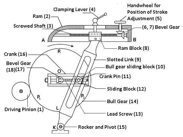
Rotation of the bull gear will make the crankpin revolve at a uniform speed.
The sliding block which is mounted upon the crankpin is fitted within the slotted link. The slotted link which is also known as the rocker’s arm is pivoted at its bottom end and attached to the frame of the column.
The upper end of the rocker’s arm is forked and attached to the ram block by a pin. As the bull gear rotates causing the crankpin to rotate, the sliding block fastened to the crankpin will rotate on the crankpin circle.
And at the same time will run up and down the slot in the slotted link providing it with a rocking movement that is communicated to the ram. Thus the rotary motion of the bull gear is converted to the reciprocating movement of the ram.
You might like: Different Types of Cutting Tools & Their Uses
#2 Whitworth Quick Return Mechanism
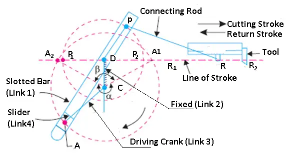
This mechanism is also used in slotting machines other than a shaper. In this type of shaper machine mechanism, the link CD (link 2) forming the turning pair is fixed. Shown in the figure.
Arrangement of Parts
Link 2 matches a crank in a reciprocating steam engine. The driving crank “CA” (link 3) rotates at a similar angular speed. The slider (link 4) connected to the crankpin at “A” moves along the slotted bar “PA” (link 1) which oscillates at a pivoted point D.
The connecting rod PR carries the ram at R to which the cutting tool is fixed. The movement of the tool is constrained along the line RD produced. i.e. along a line passing through D and perpendicular to CD.
Read also: What is a Single Point Cutting Tool? How To Use It?
Working
When the driving crank CA moves from point CA1 to CA2. (or the link DP from the point DP1 to DP2) through an angle α in the clockwise direction, the tool moves from the left-hand end of its stroke to the right-hand end by a distance of 2 PD.
Now when the driving crank moves from the point CA2 to CA1. (or the link DP from DP2 to DP1) through an angle β in the clockwise direction, the tool moves back from the right-hand end of its stroke to the left-hand end.
A little consideration will show that the time taken during the right movement of the ram (i.e. during the forward stroke) will be equal to the time taken by the driving crank to move from CA1 to CA2.
Similarly, the time needed during the right-to-left movement of the ram (or during the idle or return stroke) will be equal to the time taken by the driving crank to move from CA2 to CA1.
Since the crank link CA rotates at a uniform angular velocity, thus, the time taken during the cutting stroke (or forward stroke) is more than the time taken during the return stroke.
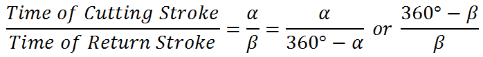
In other words, the mean speed of the ram during a cutting stroke is less than the mean speed during the return stroke. The ratio between the time taken during the cutting and return stroke is given by the formula shown in the
You might like: How To Perform Knurling Operation? Types & Uses
#3 Hydraulic Shaper Mechanism
In this type of shaper machine mechanism, the ram is moved forwards and backward by a piston moving in cylindrical placed under the ram.
The machine consists of a constant discharge oil pump, a cylinder, a valve chamber, and a piston. The Piston-rod is bolted to the ram body. As shown in the figure.
Arrangement and Working
The oil under high pressure is drawn from the reservoir. The oil is passed through the valve chamber to the right side of the oil cylinder exerting pressure on the piston.
This cause the ram connected to the piston to perform a forward stroke. Any oil present on the left side of the cylinder is discharged to the reservoir through the throttle valve.
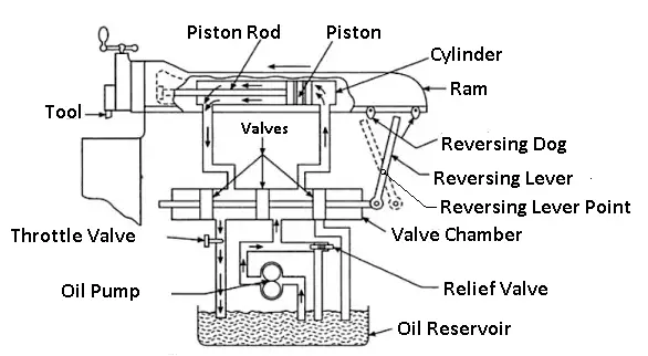
At the end of a forward stroke, the shaper dog hit the reversing lever causing the valves to alter their positions within the valve chamber.
Oil under high pressure is now pumped to the left side of the piston causing the ram to perform a return stroke. Oil present on the right side of the piston is now discharged to the reservoir.
At the end of the return stroke, another shaper dog hits against the reversing lever altering the direction of the stroke of the piston and the cycle is thus repeated.
The quick return is affected due to the difference in the stroke volume of the cylinder at both ends. The left-hand end is smaller due to the presence of the piston rod.
As the pump is a constant discharge one, within a fixed period, the same amount of oil will be a pump into the right or to the left-hand side of the cylinder.
This will mean that the same amount of oil will be packed within a smaller stroke volume causing the oil pressure to rise automatically and increase the speed during the return stroke.
The length and position of the stroke are adjusted by shifting the position of reversing dogs. The cutting speed is changed by controlling the throttle valve which controls the flow of oil.
When the throttle valve is lost the excess oil flow cut through the relief valve to the reservoir maintaining uniform pressure during the cutting stroke.
You might like: What is Turning Operation? [Definition, Types, Procedure]
#4 Automatic Table Feeding Mechanism of Shaper
The automatic feed mechanism of the table is very simple. This is done by rotating a ratchet wheel, mounted at the crossfeed screw. This enables a corresponding equal rotation of the crossfeed screw after each stroke.
Read also:
- Lathe Machine: Parts, Types, Operations, Accessories, Attachments
- Planer Machine: Parts, Types and It’s Working Principle
Arrangement of parts
It consists of a slotted disc, which carries a T-slot, as shown in the figure. In this slot is fitted an adjustable pin and to this is attached a connecting rod. The other end of the connecting rod is attached to the lower end of the rocker arm of the pawl mechanism.
The rocker’s arm swings about the screw C, and at its upper end carries a spring-loaded pawl, as shown.
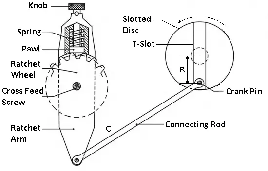
Working
Note, that the lower end of the pawl is beveled on one side.
This arrangement helps the power feed to operate in either direction, but the same should be set to operate during the return stroke only. If otherwise, the mechanism will be subjected to severe stress. In some latest types of shapers, can-driven feed mechanisms are provided which are more efficient and provide a wider range of feed.
Variation in the feed can be provided by varying the distance R between the disc center and the center of the adjustable pin. The larger the said distance greater will be the feed and vice versa.
The amount of feed to be given depends upon the type of finish required on the job. For rough machining, heavier cuts are employed, and thus, a coarse feed is needed. Against this, a finer feed is employed in finishing operations.
The slotted disc at its back carries a spur gear which is driven by the bull gear. As the disc rotates through this gear the adjustable pin, is eccentric with the disc center.
This causes the connecting rod to reciprocate. This, in turn, makes the rocker’s arm swing about the screw C to move the pawl over one or more teeth. Thus transmit an intermittent motion to the crossfeed screw which moves the table.
You can watch this video to get better-understanding knowledge on the shaper machine:
Download Pdf of this article
Conclusion
So now, we hope that we have cleared all your doubts about the Shaper Machine Mechanism. If you have still any doubts about the “Shaper Machine Mechanism” you can contact us or ask in the comments.
That’s it thanks for reading. If you like our article then please share it with your friends. If you have any questions about any topic you can ask in the comment section.
Subscribe to our newsletter to get notified when we upload new posts.
You may be interested in reading these articles:
- Different Types of Drilling Machines
- What is Gear Cutting? Their Pros and Cons
- What are the Different Types of Chips In Metal Cutting?
- 12 Different Types Of CNC Machines Explained
- Types of Spanners and Their Uses [Full Guide]
- What is Reamer? Different Types of Reamers
- 14 Types of Grinding Machines [Complete Guide]
- Different Types of Lathe Attachments and Accessories
- Up Milling and Down Milling: What’s the Difference?
- 9 Different Types of Sheet Metal Operations