In this post, we explain what is Modified Rankine Cycle its processes with p-v and t-s diagram.
Modified Rankine Cycle with P-v and T-s Diagram
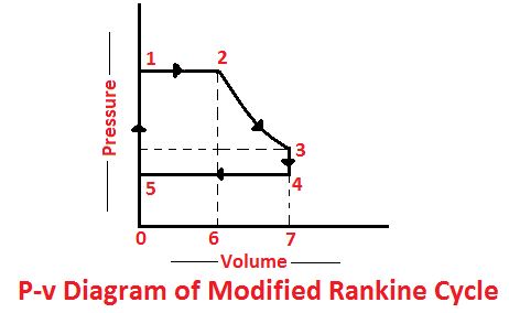
Modified Rankine Cycle: We have seen in the Rankine cycle, that the steam is expanded to the extreme toe of the p-v diagram ( at point 3) as shown in the figure. But in actual reciprocating steam engines, it is found to be too uneconomical (due to large size of the cylinder) to expand steam to the full limit (i.e. up to the point 3).


It may be noted that the diagram is very narrow at the toe, and the amount of work done (represented by area 5-3-6) during this final portion of the expansion stroke is extremely small. In fact, it is too small to overcome even the friction of the moving parts in the steam engine.
The expansion of the steam, therefore, is carried on in the engine cylinder at a pressure higher than that of the condenser pressure or exhaust pressure or backpressure. This is higher pressure is known as releases pressure (P5).
In order to overcome the above-mentioned difficulty, the Rankine cycle is slightly modified. In a modified Rankine cycle, the expansion stroke of the piston is stopped at point 5 by cutting the toe of the Rankine cycle, and the steam is exhausted from the cylinder at a constant volume.
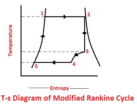
This causes a sudden drop in pressure from P5 to P6. The expansion of steam is, therefore completed by constant volume line 5-6 as shown on P-v and T-s diagram in the figure. By doing so the size of the cylinder and stroke length is considerably reduced.
Read Also:
- Rankine Cycle: Processes with P-v and T-s Diagram
- Dual Combustion Cycle Processes with [P-v and T-s Diagram]
The efficiency of Modified Rankine Cycle
Consider a modified Rankine cycle whose processes are shown in the figure.
- P1 = Pressure of steam at point 1.
- v1 = Volume of steam at point 1
- H1 = The total heat of steam at point 1,
- E1 = Internal energy od steam at point 1,
- P2, V2, H2, E2,= Corresponding valves of steam at point 2
- P4 = Backpressure of steam at point 4,
- H4 = Sensible heat of water at point 4.
We know that the area 1260 (i.e. work done during constant pressure process 1-2)

Similarly, area 2376 in figure (i.e., work done during pressure expansion 2-3)

And area 0547 in figure (i.e., work done constant pressure process 3-4)


We know that heat supplied per cycle


Note
In S.I units,

That’s it, thanks for reading. If you have any questions about the “Modified Rankine Cycle” tell us in the comments. If you like this article please share with your friends.
Read Next:
Very nice
Thanks