Rankine Cycle
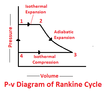
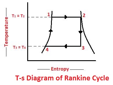
The Rankine cycle is a modified form of Carnot cycle, in which the isothermal compression (3-4) is continued unit the steam is condensed into water. A Carnot cycle, using steam as a working substance, is represented or p-v and t-s diagram as shown in the figure.
Consider 1kg of water at pressure P1 and absolute temperature T1 as represented by point 1 in the figure. The cycle is completed by the following four processes.
Read also:
- Carnot Cycle: Principle Processes, Efficiency with [P-v and T-s Diagram]
- Four Stroke Diesel Cycle Engine and Its Working [Explained with P-v and T-s Diagram]
Stages of Rankine Cycle
The following are the four stages of an ideal Rankine cycle:
- Isothermal expansion
- Adiabatic expansion
- Isothermal compression
- Warming operation
1. Isothermal Expansion
The water is isothermally converted into dry saturated steam at a constant temperature (T1) and pressure (P1). The dry state of steam is expressed in point 2. It means that the temperature T2 (i. e. at point 2) and pressure P2 (i. e. at point 2) is equal to temperature T1 and pressure P1 respectively.
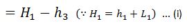
This isothermal expansion is represented by curve 1-2 in p-v and t-s diagrams in Fig. We know that the heat absorbed during isothermal expansion by water dring its conversion into dry steam is its latent heat (i.e. H1 = L).
2. Adiabatic Expansion
The dry saturated steam now expands adiabatically. The pressure and temperature fall from P2 and T2 to T3 respectively with a dryness fraction x2. As no heat is supplied or rejected during this process, there is no change of entropy. The adiabatic expansion is represented by the curve 2-3 as shown in Fig.
3. Isothermal Compression
The wet steam is now isothermally compressed at constant temperature (T3) and pressure (p3) unit the whole steam is condensed into water. IT means that the temperature T4 (i.e. at point 4) and pressure P4 is equal to the temperature T3 and pressure P3 respectively.
The isothermal compression is represented by curve 3-4 on p-v and T-s diagram in Fig. The heat rejected by steam is its latent heat ( equal to x3 L3).
4. Warming Operation
The water is now warmed at constant volume from temperature T4 to T1. Its pressure also rises from P4 to P1. The heat absorbed by water dring this operation is equal to the sensible heat or liquid heat corresponding to the pressure P1 i. e. equal to sensible heat at point 1 minus sensible heat at point 4 (i.e. equal to h1- h4).
But sensible heat at point 4 is equal to sensible heat at point3. Thus heat absorbed during warming operation is equal to (h1-h3).

= Heat absorbed during isothermal expansion+ Heat absorbed during the warming operation
And heat rejected during the cycle

= Heat absorbed – Heat rejected

And efficiency (also called Rankine efficiency),
Note on Rankine Cycle
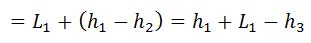
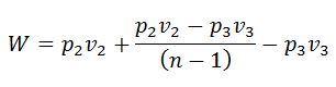
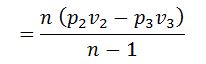
If the equation of steam (2-3) is not adiabatic and follows the general law pvn = constant, then work done during the process will not be (H1 – H3). The work done in this case will be given by the relation:
That’s it. Thank you so much for reading our blog. If you have any questions about the “Rankine Cycle” ask in the comments section. If you like this article share it with your friends.
Want free PDFs direct to your inbox? Then subscribe to our newsletter.
Download PDF of this article:
Read Next:
this wonderful . how can i get he PDF ?
Thanks. The PDF file has been sent to your inbox.