In this article, you will learn what is planetary gear? Its design, parts, functions, advantages, and uses are explained with Pictures. If you need a PDF file? You can download it at the end of the article.
What is Planetary Gear?
Planetary gears are at the heart of modern engineering and are used in basic plant machinery to electric vehicles. These are also known as epicyclic gears, consist of two gears so that the center of one gear rotates around the center of the other.
A carrier is placed to connect the centers of the two gears and rotates planet and sun gear mesh so that their pitch circles roll without slipping. A point on the pitch circle of the planetary gear outlines an epicycloid curve. In this case, the sun gear is fixed and the planet gears rotate around the sun gear.
In the early 1900s, the first transmission that used planetary gears was done by the Wilson-Pilcher automobile manufactured in the UK. Nowadays, most engineers use planetary gears in applications that require properties such as high torque density, operational efficiency, and durability.
Read Also: How Ignition Distributor works in an Engine? [PDF]
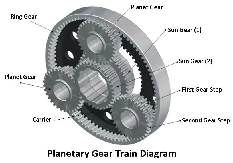
Parts of Planetary Gear Set
Following are the main parts of a planetary gear set:
- Sun gear (central gear)
- Multiple planet gears
- Ring gear (outer gear)
- Planet carrier
#1 Sun Gear (Central Gear)
In a planetary gearbox, the sun gear drives the surrounding planetary gears which are fixed to a carrier in order to avoid slipping during operation. As the sun gear is driven, the planetary gears rotate the ring gear (also known as outer gear).
#2 Multiple Planet Gears
Usually, the epicyclic gear has two gears, one planet gear meshes with the sun gear, while the other meshes with the planetary ring gear. These are used as speed reducers. They are used to slow down motors and increase torque.
The primary and main function of planetary gears is to transmit torque and to change the speed of rotation or torque between the input and output shaft.
#3 Ring Gear (Outer Gear)
The load from the sun gear is distributed to several planet gears that are used to drive either the outer ring, shaft, or spindle. The ring gear rotates in the same direction as the sun gear, thus providing a reverse direction.
#4 Planet Carrier
The planet carrier holds the planet gear which rotates around itself with a rotation that is the opposite of the planet carrier. It usually connects the centers of two gears and provides support for them to roll without slipping.
Read Also: What is a knuckle joint and how does it work? [PDF]
Construction of Planetary Gear
A planetary gear train is a very general term as the concept is very adaptable, basically, it involves. Three gears, a sun gear, a planet gear, and a ring gear, and many gear ratios can be obtained from a small volume as compared to other types of gear trains take up more space.
Unlike simple gear trains, a planetary gear train requires defining more than one input to obtain a specific output. Many outputs can be obtained by fixing a gear, that is making it stationary, giving input to another gear, and taking the output from the third gear.
The sun gear is appropriately found in the center of the assembly. It meshes with the teeth of the planetary pinion gears, planetary pinion gears are small gears fitted into a framework called planetary carrier.
This is made up of cast iron, aluminum, or steel and is designed with a shaft for each of the planetary pinion gears, the planetary pinions surrounded the sun gear’s center axis and they are surrounded by the annulus which is the largest part of the simple set.
The sun is the center of the solar system with the planets rotating around it and hence the name planetary gear set.
Read Also: What are the different types of propeller shafts used in automobiles?
Working of Planetary Gear
Each member of a planetary gear set can revolve or be held at rest, power transfer through a planetary gear set is only possible. As one of the members is held at rest, the two of the members are locked together.
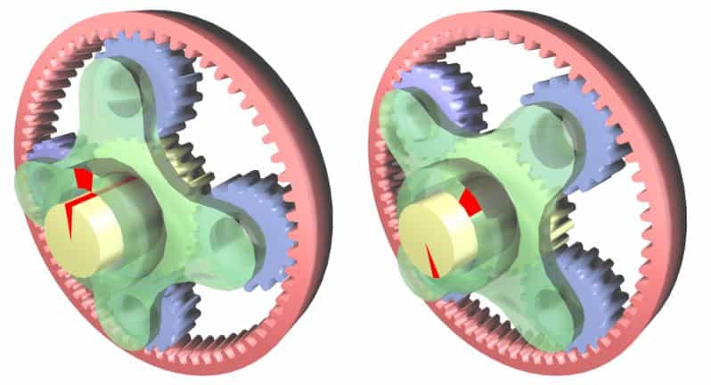
When no member is held or locked, neutral conditions exist. Any one of the three members can be used as the driving or input member at the same time another member might be kept from rotating ad thus becomes the stationary member the third member become the output member.
Depending on which member is the driver, which is held, and which is driven, either a torque increase or a speed increase is produced by the planetary gear set. In addition, the output direction can also be reversed through various combinations.
In the combinations, both the ring gear and the sun gear are input members, they turn clockwise at the same speed, the internal teeth of the clockwise turning ring gear try to rotate the planetary pinions clockwise as well but the sun gear, which rotates clockwise tries to drive planetary pinions counter clockwise, these opposing forces lock the planetary pinions against rotation.
So the entire planetary gear set rotates as one complete unit providing direct drive.
Read Also: Different Types of Transmission System and Their Uses
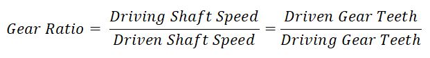
Planetary Gear Train Ratio
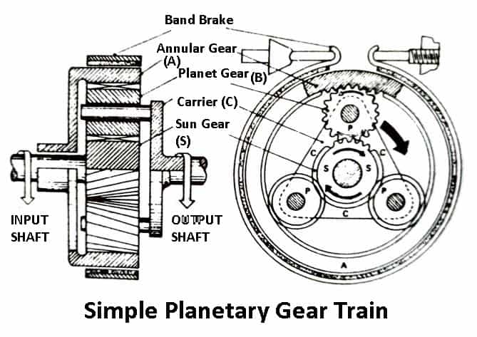
An epicyclic single-stage train consists of an internally toothed annular (ring) with a band brake encircling it. At the center of this gear is the sun gear S, which is part of the input shaft. The sun gear and annular gear are joined by a series of pinion gears P mounted on a carrier C and integral with the output shaft.
For transmission of torque, either the sun gear, carrier, or annular gear should be placed stationary in position.
The situation is considered when only the annular gear is stationary. When the input sun gear shaft is driven keeping the annular gear band brake fixed, the planet gears simultaneously rotate around their axes and revolve around the input sun gear axis along the inner circumference of the annular gear.
Therefore, the carrier and output shafts support the planet-gear axes, also rotate, but at a slower speed than the input shaft.
Let,
- TA = number of teeth on annular, internal or ring gear
- TS = number of teeth on sun or centre gear
- TP = of teeth on planet gear
- TC = number of effective teeth on arm or planet carrier
Also, TA = TS + 2TP and TC = TS + TA
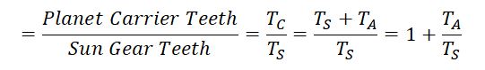
First Gear Ratio
The annular gear is held stationary and the planet carrier is driven by the power supplied to the sun gear.
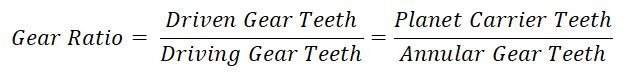
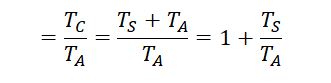
Second Gear Ratio
The sun gear is held stationary. The planet carrier is the driven member and the annular gear is the driving member.
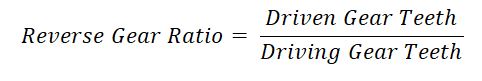
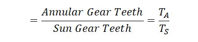
Reverse Gear
Here the planed carrier is held stationary. The annular gear is driven by the sun gear to which the power is applied.
Advantages of Planetary Gear
- It provides a more compact unit operating about a common central axis.
- The gear and gear housings are comparatively smaller in overall dimensions.
- These gear set is more flexible compared to a normal gear set.
- These types of gear trains occupy less pace.
- This gear has high gear ratio and more torque.
- It is usually compact in size.
- Instead of having the load on only one pair of gears, it is distributed over several gear wheels.
Disadvantages of Planetary Gear
- The general cost of a planetary gear system will be higher than a conventional gearbox.
- The design and manufacture of planetary gears are quite complex and also difficult.
- Determining the efficiency of a planetary gear system would be challenging.
- The gear system requires the gearing to be precise so it is quite difficult.
- Some types of planetary gearing arrangements make more noise during operation.
- To ignore any additional gearing, the driving member and the driven member must converge.
Applications of Planetary Gear
- These gears are commonly used to improve torque in robots.
- In addition, it is also used in printing presses to reduce the speed of the rollers.
- It is used in packaging machines for reproducible products in industries.
- Furthermore, it is also useful in drives such as wheel drive, track drive, conveyor, slew drive, hoist drive, and winch drive.
- They are also used in pumps, coil tubing injectors and cutter head drives.
Wrapping It Up
Planetary gears are commonly used in various industries. Since the gear is one of the most important components of the planetary gear mechanism, these gears will affect the entire transmission system.
These gears have many advantages, such as increased torque, less comparable size, less weight, better efficiency, and many more.
So for now, I hope I’ve covered everything about “Planetary Gear“. If you still have any doubts or questions regarding this topic, you can contact us or ask in the comments, I will reply to you. If you liked it, then share this in your friends circle and spread the knowledge.
Want free PDFs direct to your inbox? Then subscribe to our newsletter.
Download PDF of this article:
In addition, we have also written a lot of articles, some of which are mentioned below:
Nice blog about Planetary gearheads. Very well explained planetary gearheads with Introduction, types and principle
Thanks for your feedback.
Hi. The information’s on Planetary Gears are very useful and thank you very much.
You’re welcome.