In this article, you’ll learn what are different shaper operations performed on shaper machines.
Shaper Operations
A shaper is a handy machine tool primarily designed to produce a flat surface by a single-point cutting tool but it may also be used to do many other operations.

Read also:
Shaper Machine Operations
The following are the shaper machine operations:
- Machining horizontal surface
- Vertical surfaces
- Angular surfaces
- Irregular surfaces
- Cutting slots, grooves, and keyways
- Machining splines or cutting gears.
The various shapes of surfaces are the result of either one or a combination of more than one of the above operations.
#1 Machining Horizontal Surfaces
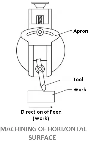
It is the most common shaper machine operation. In this, the work is fed horizontally under the reciprocating tool and the surface produced is horizontal and flat. The work is either held in a vice or clamped directly on the machine table, depending upon its size. The tool is held in a proper tool holder.
It is set at a proper inclination and the correct height above the work, as described later in this article. The depth of cut is adjusted and the machine gets started.
Crossfeed to the table is given initially by hand until the cut starts. After that power feed can be employed. After the cut is finished, the machine is stopped and the work is inspected. If more material is to be removed, the procedure is repeated until the desired surface is obtained.
A special precaution is required in setting the tool for horizontal cutting. The tool should be held vertically in such a way that its cutting edge points in a direction slightly away from the work, as moves, due to the cutting pressure, it will move away from the work instead of digging into it.
Another precaution to be taken in the toolset is that its cutting edge should not be projected much below the tool holder. The vertical slide of the tool head should not be made to overhang too far below the ram. If otherwise, the tool will be weakened and subjected to under strain.
#2 Machining Vertical Surfaces
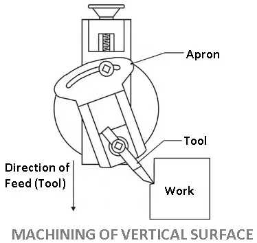
A vertical cut is made while machining the end of a workpiece, squaring up a block, or cutting a shoulder. The work is attached in the vice or directly on the table and the surface to be machined is carefully aligned with the axis of the ram.
A side cutting tool is set on the tool post and the position and length of stroke are adjusted. The vertical slide is set accurately at zero position.
This is necessary to enable the tool to move upwards and away from the work during the
The
#3 Machining Angular Surface
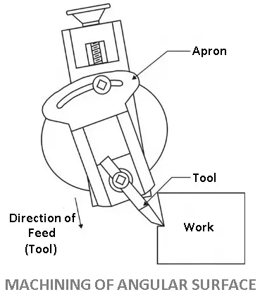
In this shaper machine operation, an angular cut is done at any angle other than a right angle to the horizontal or the vertical plane. The work is set on the table and the vertical slide of the tooth head is swiveled to the required angle either towards the left or towards the right from the vertical position.
The apron is then further swiveled away from the work so that the tool will clear the work during the
The angular surface can also be machined in a universal shaper or by using a universal vice without swiveling the tool head.
#4 Machining Irregular Surfaces
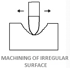
A shaper can also produce a contoured surface, i.e. a convex or concave surface or a combination of any of the above surfaces. To manufacture a small contoured surface a forming tool is used.
If the curve is large, power cross feed in conjunction with manual down feed is so adjusted that the wool will trace the required contour. If the contour (workpiece shape) has too many ups and downs both the feeds are operated by hand.
For machining irregular surfaces a round nose tool is used. For a shallow cut, the apron may be set vertically but if the curve is quite sharp, the apron is swiveled towards the right or left away from the surface to be cut. The figure shows the machining of a concave surface using a round-nose tool.
#5 Cutting Slots and Keyways
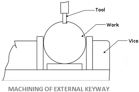
With suitable tools, a shaper can very conveniently machine slots or grooves on work or cut external keyways on shafts and internal keyways on pulleys or gears.
For cutting slots or keyways on shafts and internal keyways on pulleys or gears. For cutting keyways or slots a square nose tool similar to a parting tool is used.
External keyways are made on a shaft by first drilling a hole at the blind end of the keyway. The diameter of the hole should be 0.5 to 0.8mm oversize than the width of the keyway and the depth should be about 1.5mm larger than the depth of the keyway.
This is important to leave clearance on the tool at the end of the stroke. The length and position of the stroke are carefully adjusted so that the stroke will terminate exactly at the clearance hole. The speed is reduced while cutting keyways.
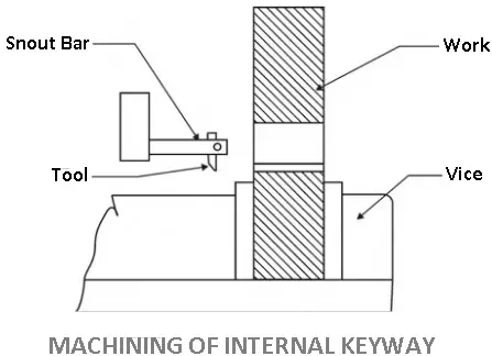
Internal keyways are cut by holding the tool on a special tool holder so that the tool post will not hit against the work at the end of the stroke.
The clapper block is locked in the clapper box to prevent the tool from lifting during the return stroke. Lubrication is necessary in the work to prevent the cutting edge of the tool from wear due to dragging.
#6 Machining Splines or Cutting Gears
This type of shaper machine operation is done by using an index center, illustrated in a gear or equally spaced splined may be cut.
The work is placed between two centers, and a spline is cut similar to the cutting of a keyway. After the first spline is cut, the work is rotated through a predetermined amount by using the index plate and index pin.
The periphery of a gear blank is divided, and equally spaced grooves are cut using an index plate having proper hole circles. While cutting gear a forming tool is used.
Conclusion
If you like this article on “Shaper Machine Operations” then share it with your friends. Have any questions or doubts just leave a comment below in the comment box.
Subscribe to our newsletter to get notifications of our new Engg posts.
Download PDF of this article

Read next about machines like