In this article, you’ll learn what is single point cutting tool? Its diagram, construction, geometry, nomenclature, and applications all are explained with pictures.
Also, you can download the PDF file at the end of this article.
What is a Single Point Cutting Tool?
A single point cutting tool refers to a tool with a single cutting edge used in the machining process to remove material from a workpiece.
A single-point cutting tool is so named because it only has one edge, unlike a multi-point cutting tool, which has multiple edges.
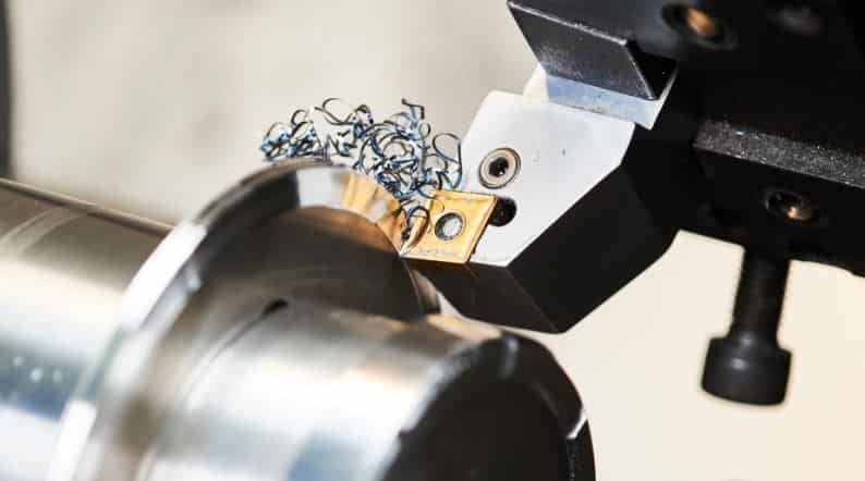
On lathes and milling machines, single-point cutting tools are frequently used for turning, facing, and boring operations. Typically, the tool’s body is made of a more durable, more flexible material, such as steel. In contrast, the cutting edge is made of a hard, wear-resistant material, such as tungsten carbide or ceramic.
Tool cutting edges are shaped and ground to produce the desired geometry, such as sharp points for drilling and rounded noses for turning.
There are many factors that influence the cutting properties of tools, including their surface finish, accuracy of machined surfaces, and their angle and shape.
Let’s now discuss the construction and parts of a single-point cutting tool.
Read Also: What are the different Types of Lathe Cutting Tools Used in Lathe?
Construction of Single Point Cutting Tool
This tool includes a shank and a point that has been sharpened for cutting. There are four parts to this tool: the face (which slides the chips), the side flanks or major flanks, the end flanks or minor flanks, and the base.
The neck of the cutting tool connects the shank to the cutting edge. When machining deep grooves or cavities, it provides clearance. The tool’s cutting edge is the portion that removes the material from the workpiece. Usually, it consists of a harder, stronger material than the shank.
The portion of the cutting edge facing the cutting motion is the rake face. It is angled to let the chip pass through and reduce cutting forces. The part of the cutting edge that faces away from the cutting motion is known as the flank face. It helps in controlling chip flow and supports the cutting edge.
The point or edge of the cutting tool that comes into contact with the workpiece is called the tip. It is usually rounded or angled to reduce the possibility of chipping or breaking.
Read Also: 22 Different Types of Lathe Machine Operations [Complete Guide]
Types of Single Point Cutting Tools
Single point cutting tools are classified into two types:
#1 Single Point Cutting Tool
This tool has only one cutting point or tip.
Examples: Lathe machines and planning machine tools are two common examples of single point cutting tools.
#2 Multi-Point Cutting Tool
This tool has multiple cutting points or tips.
Examples: Milling cutters, grinding wheels, drill tools, and other multi-point cutting tools are common examples.
Single Point Cutting Tools Materials
Single-point cutting tools are usually made from hard, wear-resistant materials to withstand the high temperatures and stresses generated during machining operations.
The choice of material will depend on a number of factors, including the material being machined, the cutting conditions, and the desired tool life.
Single point cutting tools are frequently made of the following materials:
#1 High-speed Steel (HSS)
HSS has been alloyed with tungsten, molybdenum, or cobalt to increase its toughness and wear resistance. However, HSS tools are not as wear-resistant as other tool materials. They are still relatively affordable and capable of processing a wide variety of materials.
#2 Carbides
The material tungsten carbide (WC) or a mixture of tungsten carbide and cobalt is used to make carbide tools. Compared to HSS tools, carbide tools can machine harder materials at higher speeds and are much harder and more wear-resistant.
#3 Ceramic Materials
Ceramic tools are extremely durable and resistant to wear because they are made of silicon nitride (Si3N4) or aluminum oxide (Al2O3). They are used to machine hardened steels, high-temperature alloys, and other challenging-to-machine materials. Though, they are fragile and can chip or break easily.
#4 CBN (Cubic Boron Nitride) & Diamond
The hardest and most wear-resistant cutting tool materials are CBN and diamond. They are used to machine extremely hard materials like hardened steels and superalloys. However, due to their high cost, they are usually employed in high-precision or high-production machining operations.
#5 Cemented Carbide
The material used to create these tools is cemented carbide, a hard and wear-resistant substance. It is a composite material created by mixing tungsten carbide particles with a metallic binder, usually cobalt. These tools are utilized in machining processes like turning, milling, and drilling.
Read Also: Types of Metals: Their Properties and Applications [Full Guide]
Single Point Cutting Tool Nomenclature and Geometry
Nomenclature is the methodical naming of various components and angles of a single point cutting tool. The full nomenclature of a single-point cutting tool is displayed in the above image.
A list of the components of a typical single-point cutting tool nomenclature is provided below:
- Shank
- Face
- Base
- Nose or cutting point
- Nose radius
- Heel
- Flank
- Cutting edge
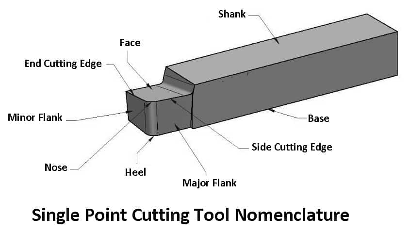
#1 Shank
The tool holder on the machine recognizes the shank, which is the main body of the single point cutting tool. In terms of volume, it makes up a bigger portion of the tool.
#2 Face
The face of the tool is where chips move upward and outward during the machining process.
#3 Base
In single-point cutting tools, the bottom surface on which the tool stands is called the base.
#4 Nose or Cutting Point
There is a point in front of the tool where the side and end cutting edges meet, known as a tool nose. It is also referred to as the tool’s cutting point.
#5 Nose Radius
The radius of the nose is known as the nose radius, and it contributes to better surface finishing and longer tool life.
#6 Heel
The heel of a single-point cutting tool is defined as the point at which the flank and base surfaces meet.
#7 Flank
The major flank and minor flank are the two flank surfaces found on cutting tools. A vertical surface next to the side cutting edge is the major flank. A minor flank is a vertical surface that lies close to the cutting edge at the end.
However, neither surface is actually vertical; rather, they both have a slight incline toward the base. The cutting face is also referred to as the flank.
#8 Cutting Edge
Cutting edges are those that are used to remove material during the machining process. Cutting Edges are produced by faces and cutting surfaces. Single-point cutting tools have two cutting edges: a side cutting edge and an end cutting edge.
- Side cutting edge: Edge or line formed by the face and a minor flank or cutting surface.
- End cutting edge: The face and the major flank or major cutting surface forms the end cutting edge, just like the side cutting edge.
Read Also: Different Types of Lathe Attachments and Accessories [Explained]
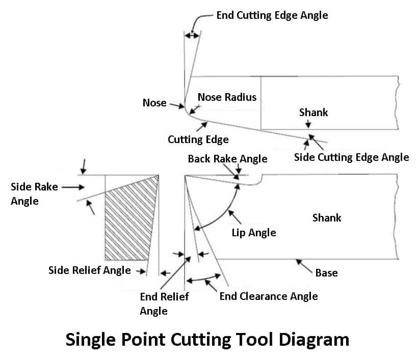
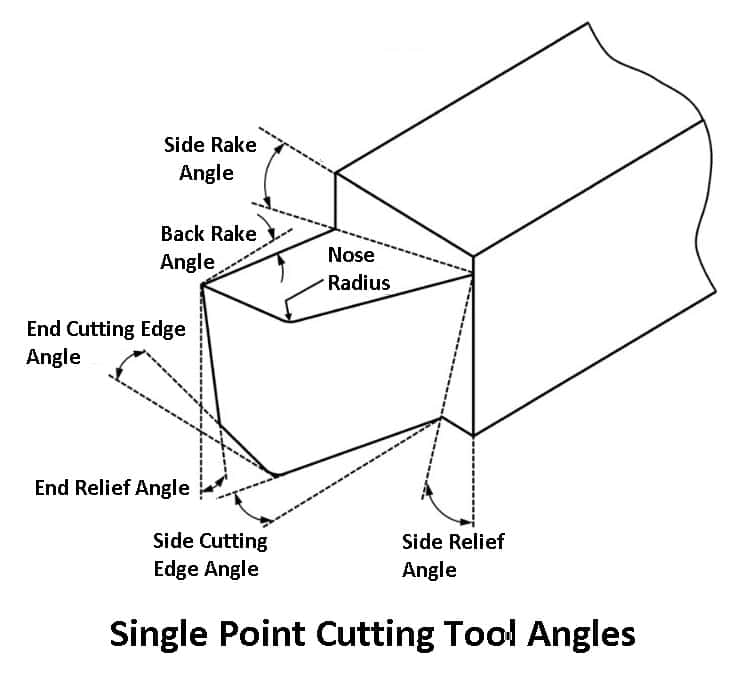
Single Point Cutting Tool Angels
- Rake angle
- Back rake angle
- Side rake angle
- Relief angle
- End relief angle
- Side relief angle
- Cutting edge angle
- Side cutting edge angle
- End cutting edge angle
- Clearance Angle
#1 Rake Angle
An essential geometric component of a single point cutting tool is the rake angle. The angle formed by the cutting edge and a line perpendicular to the surface of the workpiece is known as the rake angle.
a) Back Rake Angle
The angle formed between a single-point cutting tool’s face and a horizontal line parallel to the tool’s baseline is known as the back rake angle.
If the side cutting edge slopes away from the point and toward the shank, the back rack angle is positive. If the slope is reversed, the back rack angle is negative.
b) Side Rake Angle
The side rake angle is measured in a plane perpendicular to the base and the side cutting edge of the tool. It is the angle formed between the tool’s face and a line parallel to the tool’s base.
If the slope is toward the cutting edge, the side rack angle is negative. Also, if the slope is away from the cutting edge, the side rack angle is positive.
#2 Relief Angle
The flank and a perpendicular to the machined surface together make up the relief angle. It makes sure that the tool does not make contact with the machined surface while cutting.
a) End Relief Angle
The angle that forms a right angle with a minor flank or minor cutting face and a perpendicular line to the base is known as an end relief angle.
b) Side Relief Angle
The angle that forms a right angle with the side between the major flank or major cutting face and the perpendicular plane to the base is known as the side relief angle.
#3 Cutting Edge Angle
The angle created by the cutting edge and a line perpendicular to the machined surface is known as the cutting edge angle. It is the standard angle for turning operations is 90 degrees.
a) Side Cutting Edge Angle
It is the angle made by a perpendicular line to the machined surface and the side cutting edge. It has an impact on the chip’s width during cutting.
b) End Cutting Edge Angle
It is the angle made by a perpendicular line to the machined surface and the cutting edge’s end. It affects the chip’s thickness when cutting.
#4 Clearance Angle
The clearance angle is the angle formed by a line tangent to the machined surface and the flank. It enables the tool to move freely over the surface without bumping into it.
Read Also: Lathe Machine Formulas: Cutting speed, Feed, Depth of cut, Machining time
Advantages of Single Point Cutting Tools
Using single point cutting tools will provide you with the following benefits:
- Turning, facing, boring, and threading are the machining operations that can be performed with single-point cutting tools.
- Due to having only one cutting edge, single point cutting tools produce precise cuts.
- Compared to other types of cutting tools, like milling cutters, single point cutting tools are quite affordable.
- They are made from high-quality materials and designed to withstand high temperatures and stresses.
- Because they are simple to sharpen, these tools can keep their cutting edge and live longer.
- They are an effective option because they can rapidly remove material from a workpiece.
- Multiple machining operations can be performed with a single point cutting tool. This eliminates the need for additional tools and lowers inventory costs.
Disadvantages of Single Point Cutting Tools
Despite its advantages, single point cutting points also have some disadvantages that limit their use. Below is a list of some of them.
- Compared to milling cutters, single-point cutting tools have a limited cutting speed, resulting in slower machining times.
- Due to their limited geometry options, single point cutting tools may not be suitable for all machining operations.
- If single point cutting tools are not used properly, workpiece damage may result.
- As opposed to other cutting tools, these tools require a higher level of skills to use.
- The use of single point cutting tools may be limited in some applications because they may not be suitable for all materials, such as hard or brittle materials.
Read Also: What is Lathe Chuck? Types, Parts, Working with [Complete Guide]
Applications of Single Point Cutting Tools
Single-point cutting tools are employed in various processes, including turning, boring, facing, and threading. In manufacturing processes, they are often used to remove material from a workpiece and shape it into the desired shape.
Here are some examples of specific applications for single-point cutting tools:
#1 Turning
In turning operations, single point cutting tools are commonly used to remove material from a rotating workpiece. To shape the workpiece into a cylinder, the tool is fed into the workpiece while mounted on a tool holder.
#2 Boring
Boring is a technique used to enlarge an existing hole in a workpiece. During this process, the material inside the hole is removed using a single point cutting tool.
#3 Facing
Making a flat surface on the end of a workpiece is known as facing. In this process, material from the workpiece’s end is removed until the end is flat using single point cutting tools.
#4 Threading
Cutting threads into a workpiece is the procedure known as threading. The threads are produced by removing material from the workpiece using single point cutting tools.
Closing It Up
That’s it. Thanks for reading. I hope I have covered everything about the “Single Point Cutting Tool.” It would be helpful if you could let me know if there was anything I missed or if you have any doubts about anything I wrote.
Please share this article with your friends if you find it interesting.
Want free PDFs direct to your inbox? Then subscribe to our newsletter.
Download PDF file of this article:
You might like to read more in our blog:
Great post! The detailed diagram and clear explanation of the nomenclature really helped me understand the fundamentals of single point cutting tools. I’m also interested in the materials section – it’s fascinating to see how different materials can impact tool performance. Thanks for sharing this valuable information!
Thank you! I’m glad you found the diagram and explanation helpful. I