In this article, you’ll learn what a milling machine and different types of milling machines, and more.
What is a Milling Machine?
Milling is the machining process in which the removal of metal takes place due to the cutting action of a rotating milling cutter. In a milling machine, the cutter is rotating due to the workpiece is fed against it.
This machine can hold more than one tool at a time. The cutter rotates at high speed, and because of the many cutting edges, it removes metal at a very fast rate.
The machine can also hold one or some cutters at a time. Thus, the milling machine is one of the most important machines in the workshop. In this machine, all the operations can be performed with high accuracy.
The metal removal rate is high as compared to a lathe machine, planner machine, and shaper machine. It has good accuracy and a better surface finish. This is why a milling machine finds wide application in production work.
Read Also: What is Slot Milling? Diagram, Working, Types
Types of Milling Machines
Following are the different types of milling machines:
Column and Knee Type
For general shop work, the most used type of milling machine is the column and knee type machine. The table is mounted on the knee-casting which in turn is mounted on the vertical slides of the main column.
The knee is vertically adjustable on the column so that the table can be moved up and down to accommodate work of various heights.
The column and knee-type milling machines are classified in the below-mentioned category.
- According to the various methods of supplying power to the table.
- Different movements of the table. and
- The different axes of rotation of the main spindle.
#1 Hand Milling Machine
It is simplest of all
This type of milling machine is small in size and suitable for light and simple milling operations. For Example, machining slots, grooves, and keyways.
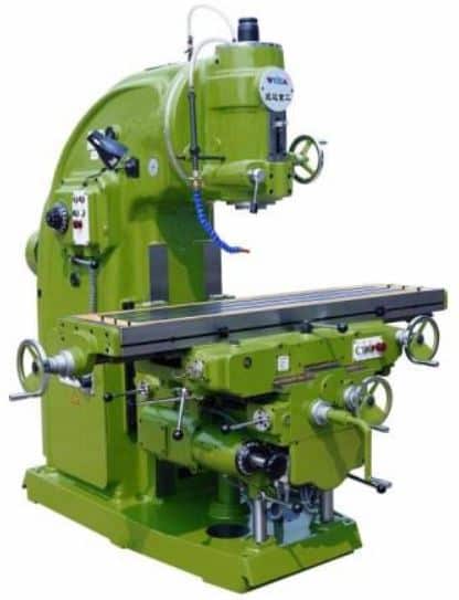
#2 Plain Milling Machine
These are much stronger than hand millers. The table feeding is done either by hand or power. the plain milling machine having a horizontal spindle is also called a horizontal spindle milling machine. The table may be fed in a longitudinal, cross, or vertical directions.
The feed is:
- Longitudinal – when the table is moved at right angles to the spindle.
- Cross – when the table is moved parallel to the spindle.
- Vertical – when the table is adjusted in the vertical plane.
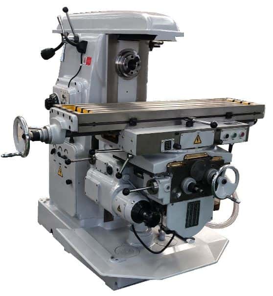
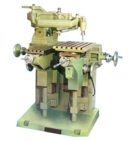
#3 Universal Milling Machine
It can be adapted to a wide range of milling operations. Here the table can be swiveled to any angle up to 45 degrees on either side of the normal position.
In addition to 3 movements, as mentioned earlier in a plain milling machine, the table may have a fourth movement when it is fed at an angle to the milling cutter. Helical milling operations can also be performed. The capacity of this type of machine is increased by using special attachments such as
- Dividing head or index head.
- Vertical milling attachment.
- Rotary attachment.
- Slotting attachment.
This machine can produce spur, bevel, spiral, twist drill, reamer, and milling cutter. All operations that are performed on a shaper can be done using a universal milling machine.
#4 Ominversal Milling Machine
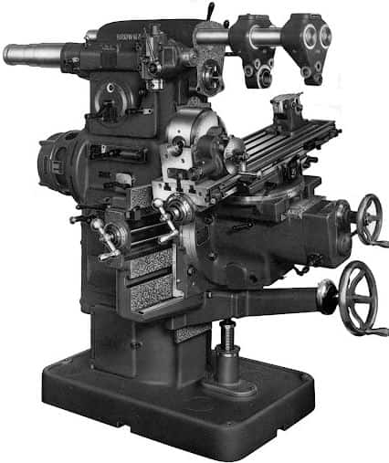
Here the table also has four movements of the universal milling machine. It can also be tilted in a vertical plane by providing a swivel arrangement at the knee.
The additional swivelling arrangement of the table helps in machining spiral grooves in reamers and bevel gears.
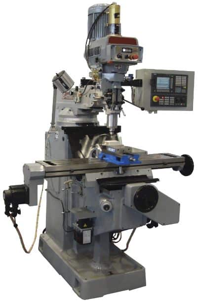
#5 Vertical Milling Machine
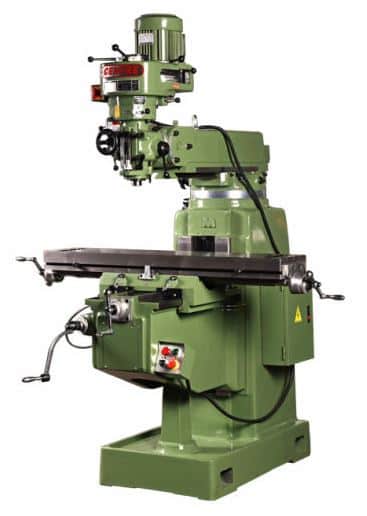
Here the position of the spindle is vertical or perpendicular to the table. This type of machine is adapted for machining grooves, slots, and flat surfaces.
The machine may be of the plain or universal type and has all the movements of the table for a proper setting and feeding of the work.
The spindle head is clamped to the vertical column which is swivelled at an angle. It allows the milling cutter fixed on the spindle to work on angular surfaces. In some machines, the spindle can also be adjusted up or down relative to the work.
Fixed Bed Type or Manufacturing Type
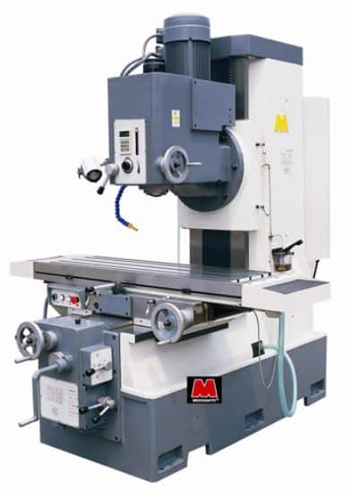
These machines are large, heavy, and rigid in construction. These machines differ from column and knee-type milling machines by the construction of their table mounting.
The table is mounted directly on the ways of a fixed bed. The table movement is restricted to reciprocating at a right angle to the spindle axis with no provisions for cross or vertical adjustment.
It is classified as simplex, duplex, or triplex based on a machine provided with single, double, and triple spindle heads respectively.
#1 Simplex Milling Machine
In these types of milling machines, the spindle, or spindle head, is capable of moving in one direction. The most typical direction of movement is vertical.
#2 Duplex Milling Machine
These types of milling machine spindles can travel in both horizontal and vertical directions.
#3 Triplex Milling Machine
These milling machines have a spindle that can move in the X, Y, and Z axes.
Planer Type Milling Machine
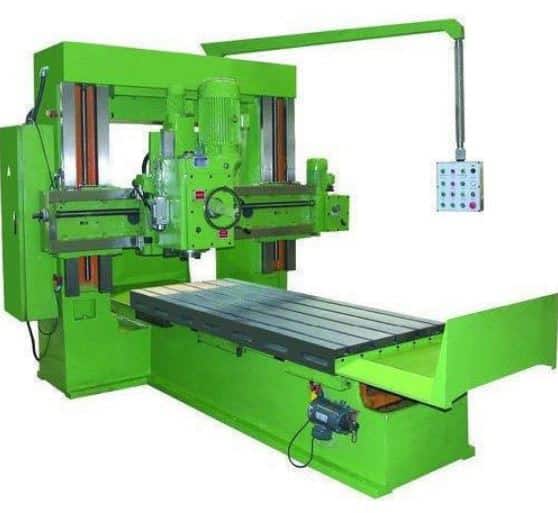
This types of milling machine are also called “Plano-Miller”. It is a massive machine used for heavy-duty work having spindle heads adjustable in the vertical and transverse direction.
It relates to a planer and is like a planing machine. This machine has a cross rail capable of being raised or lowered carrying the cutters. It has their heads, and the saddles, all supported by rigid uprights.
This arrangement of driving multiple cutter spindles enables some work surfaces to be machined. Thereby it obtains a great reduction in production time.
The essential difference between a planer and a Plano-miller lies in the table movement. In a planer, the table moves to give the cutting speed. But in a Plano-milling machine, the table movement gives the feed.
Read Also: What are the Different Types of Cutting Tools?
Special Types of Milling Machine
Milling machines of non-conventional design have been developed to suit special purposes. This machine has a spindle for rotating the cutter and provision for moving the tool or the work in different directions. The following special types of machines of interest are described below:
#1 Rotary Table Milling Machine
Here the table is circular and rotates about a vertical axis. Here cutters are set at different heights. This results in one cutter roughing the workpiece and the other cutter finishing it.
The advantage of this machine is that continuous loading and unloading of workpieces can be done by the operator, while is in progress.
#2 Drum Milling Machine
It is like a rotary table milling machine. But its workpiece supporting table is called a “DRUM” and it rotates in the horizontal axis.
The face milling cutters mounted on three or four-spindle heads rotate on a horizontal axis and remove metal from workpieces supported on both the faces of the drum. The finished machined parts are removed after one complete turn of the drum, and then the new ones are clamped to it.
#3 Planetary Milling Machine
Here workpiece is held stationary while the revolving cutter. The cutter moves in a traveling path to finish a cylindrical surface on the workpiece either internally or externally. This machine is also adapted for milling internal and external threads.
#4 Pantograph Milling Machine
A pantograph machine can duplicate a job by using a pantograph mechanism. It allows the size of the workpiece reproduced to be smaller than, equal to, or greater than the size of a template. Also used for different models for special purposes.
A pantograph is a mechanism that is generally constructed of four bars or links which are connected in the form of a parallelogram.
Pantograph machines are available in two-dimensional and three-dimensional models. The two-dimensional pantograph is used for engraving letters or other designs. Whereas three-dimensional models are employed for copying any shape and contour of the workpiece.
#5 Profiling Milling Machine
A profiling machine duplicated the full size of the template attached to the machine. Here the spindle can be adjusted vertically and the cutter horizontally across the table.
A hardened guide pin regulates the movement of the cutter. The longitudinal movement of the table and the
#6 Tracer Controlled Milling Machine
The tracer-controlled milling machine reproduces irregular or complex shapes of dies, and molds by synchronized (matched) movements of the cutter and tracing elements.
The movement of the stylus energized an oil relay system which in turn operates the main hydraulic system for the table. This arrangement is termed a servomechanism.
#7 CNC Milling Machine
The CNC machine is the most flexible milling machine, and it requires computer control to operate. This machine features a 360-degree rotating table and a three-directional spindle.
These types of milling machine can be considered as an improved version of bed-type milling machines because they have many of the same features.
Under computer commands, the movements are hydraulically controlled. All you have to do is scan the workpiece’s sketch into your computer, and it will utilize that sketch to automatically feed the workpiece through its cutters.
Conclusion
The milling machine is widely used in many industries because of the high metal removal rate, good accuracy, and better surface finish. This is why a milling machine finds a wide application in production work.
Also if you like the article on the “Types of Milling Machine” then please share it with your friends. If you have questions or suggestions let us know in the comments.
Now you can Download PDF of this article by clicking below.
Read Next:
Images Credit: Indiamart.com
FAQs
The milling machine removes material from a workpiece by rotating and moving a cutting tool such as a cutter.
In this, the cutting motion is achieved by feeding the workpiece against a rotating cutter. The workpiece is securely fastened to the table, while a multitooth cutter mounted on the arbor revolves. The cutter revolves rapidly as the material is fed.
CNC milling machines are used to precisely and accurately cut the material. It is possible to produce virtually any item and component with a CNC milling machine, as the machine can cut a wide variety of shapes and angles.
There are several different types of milling machines. Some of them include column and knee type, plain or horizontal, vertical, universal, fixed bed type, simplex, duplex, triplex, planer type, rotary table, drum type, profile milling, planetary type, tracer operated, pantograph type, and CNC milling machine.
Dear Sir
I Want a Milling machine for milling of Slabs of brass. Dimension L-2m, W-1m thickness-5 mm
The milling has to be done on both sides of the slab (0.5mm).
A continuous milling machine is required.
kindly suggest me best type of milling machine.
kind regards
Hi, thanks for your comment 🙂 to buy any machine you can check out IndiaMART.com website
Great
Thanks.
Thank you for this infromation
You’re welcome 🙂
Thank you for sharing.
You’re welcome
So your describe for million machine so beautiful and beat wise question
Thank you a lot
You’re welcome 🙂
Thank you for this reference
You’re Welcome