In this post, you’ll learn what is tolerance and types of tolerances with schematic diagram and difference between unilateral & bilateral tolerance.
Tolerances and Its Types
It can be defined as the measurement of allowable differences of a dimension or other measured or control criterion from the specified value. Tolerances have to be allowed because of inevitable of the human failings and machine limitations which prevent ideal achievement during fabrication.
To maintain economic production and facilitate the assembly of components, it is important to allow limited difference from the designed size. Because of its inevitability, tolerance constitutes engineering legality for deviation from the ideal value and like any other legal matter, formulation of tolerance given due consideration and much care and plan should go into it.
When machining we try to achieve a diameter of 50 mm, which is called basic or nominal diameter. The shaft shall be satisfied if the diameter lies between 50+0.06=50.06 mm and 50-0.06 = 49.94 mm. The dimension 50.06 mm is called the upper limit and the dimension 49.94 is called lower limit is called tolerance.
Tolerance = 50.06 – 49.94 = 0.12 mm.
Note that tolerance always is a positive quantitative number.
Read also: Vernier Caliper: Parts, Types, Working Principle, Least Count, Errors
Types of Tolerances
Following are the three types of tolerances used in measurements:
- Unilateral tolerances
- Bilateral tolerances
- Compound tolerances.
Unilateral Tolerances
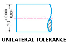
When the two limit dimensions are only above the nominal size as shown in the figure or only below the nominal size then the tolerance is said to be unilateral.
Bilateral Tolerances
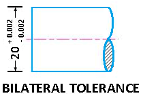
When the two limit dimension is above and below the nominal size, Then the tolerances are said to be bilateral.
Compound Tolerances
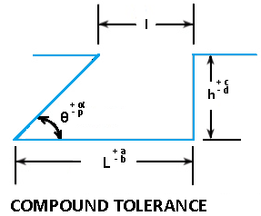
Compound tolerance is determined by the established tolerances i.e., the combination of more than one type of tolerances are called compound tolerances, the different types of tolerances may be angular, lateral etc.
For Example: In figure tolerances on dimension / are dependent on tolerances of L, h and θ. This compound tolerance on ‘l’ is the combined effect of these three tolerance. The minimum tolerance on ‘l’ will be corresponding to L-b, θ+∝ and h+c.
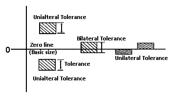
Schematic Representation of Tolerances
Different Between Unilateral and Bilateral Tolerance
Unilateral Tolerance
- Variation is made in only are direction from the nominal or basic dimension.
- The tolerances for the same allowances or type of fit can be changed without changing the nominal size of the shaft or hole.
- There are suitable for any type of production.
- Go gauges for holes and NOGO gauges for shafts can be standardised.
- Ex: Φ50
Bilateral Tolerance
- Variation is made in both direction from the nominal or basic dimension.
- The tolerances for the same allowance or type of fit can be changed by changing the nominal size of the shaft or hole.
- These are suitable for mass production.
- It is not possible to standardise.
- Ex: Φ50
Tha’s it, thanks for reading. If you have any questions about “types of tolerances” tell us in the comments. If you like this article then please share with your friends.
Read Next:
Compound tolerance was not known. Now I understand, you have explained well
I’m glad it was helpful for you.
Nice concepts, example is required for more understanding perspectives
Sure we’ll do.