In this article, you’ll learn what is an electric circuit and it’s different types of circuits with diagrams.
Also download this article in PDF format at the end of it.
Electric Circuits and Types
An electric circuit, also known as an electrical circuit, is a conductor used to move current or electricity. To establish a connection between the source of voltage and the load, a conductive wire is used. The source and load are separated by a fuse and an ON/OFF switch.
The figure represents a simple electric circuit.

Depending upon the type of current flowing, the electric circuit is classified into D.C. circuit and A.C. circuit.
Read also:
- Different Types of Resistors and Their Applications
- Different Types of Capacitors and Their Applications
Types of Electrical Circuits with Diagram
Following are the types of electrical circuits with diagram:
- D.C. Circuit
- A.C. Circuit
- Closed-circuit
- Open circuit
- Short circuit
- Series Circuit
- Parallel Circuit
- Series-Parallel Circuits
#1 D.C. Circuit
The circuit in which direct current (D.C.) flows is known as the D.C. circuit.

The figure represents the D.C. circuit. Direct current (D.C.) is a unidirectional current whose magnitude remains constant. D.C. can be represented as shown below.

#2 A.C. Circuit
The circuit in which alternating current flows is known as A.C. circuit. The simple A.C. circuit is shown in the figure.

Alternating current is a bidirectional current, whose magnitude and direction changes periodically at regular intervals of time. The A.C. can be represented as shown below.

#3 Closed-Circuit
Depending upon the condition of the circuit A.C. or D.C. circuits are classified into three circuits they are:
- Closed-circuit
- Open circuit
- Short circuit
In the closed circuit the current path is closed i.e. current starts from the positive terminal of the supply, through the line, load, neutral, and ends in the negative terminal of the supply. The closed circuit is shown in the figure.

#4 Open Circuit
In an open circuit current won’t enter back to the negative terminal of the supply i.e. current path is incomplete due to the break in the circuit. The open circuit is shown in the figure.

#5 Short Circuit
The circuit in which line and neutral wires are shorted (touch each other) is known as a short circuit. Here current returns back directly to the negative terminal of the supply, without passing through the load as shown in figure.

#6 Series Combination of Resistances:
When the resistances are connected end-to-end, as shown in the figure, they are connected in series.

In the above figure resistance R1, R2, & R3 are connected in series, across a supply voltage of ‘V’ volts. in a series circuit current through each resistance is identical, the voltage drop across each resistance is different and the sum of voltage drops is equal to the voltage applied.
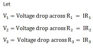
Since the voltage applied is equal to the sum of voltage drops across three resistances, the relation between V, V1, V2, and V3 is given by,
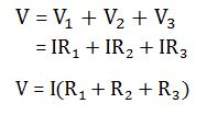
If R is the total resistance of the combination and I is the total current through the combination, then total voltage V=IR.
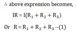
The above equation represents that the total or effective resistance of a series circuit is equal to the sum of all individual resistances connected in series.
Characteristics of a Series Combination of Resistances
- The equal current flows in all parts of the circuit.
- Individual resistors have their individual voltage drops.
- Voltage drops are addictive.
- The applied voltage is equal to the sum of individual voltage drops.
- Resistances are addictive.
- Powers are addictive.
#7 Parallel Combination of Resistances:
In a parallel combination of resistances, all the starting ends of resistances are connected to one common point and all finishing ends are connected to another common point as shown in the figure.

Consider the above figure in which R1, R2, and R3, are connected between common points A & B across a supply voltage of V volts. In parallel combination, the potential difference across all resistances is the same (i.e. V volts), the current in each resistor is different and is given by Ohm’s law and the total current (I) through the combination is the sum of individual currents through individual resistances.
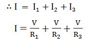
If R is the total resistance of the combination, the total current I= V/R ∴ above expression becomes,
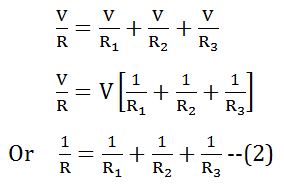
The above equation represents that the reciprocal of the total resistance of the circuit is equal to the sum of reciprocals of individual resistances connected in parallel.
Read also:
- Inductors: Types, Specifications, Working and Application
- 25 Different Types of Electrician Tools and Their Uses
Characteristics of a parallel combination of resistances
The main characteristics of a parallel circuit are:
- The voltage drop across each resistor is the same as the applied voltage.
- Individual resistors have their individual current.
- Branch current is additive.
- Conductance (1/R) is additive.
- Powers are additive.
- The total current is similar to the sum of the individual currents.
#8 Series-Parallel Combination of Resistances:
In this combination, resistances are connected in series as well as parallel as shown in the figure.

To reduce such combinations to a simpler form the following steps are adopted :
- Find the effective resistance of the parallel combination of resistances.
- Replace the parallel combination with its equivalent resistance. Now-R1 is in series with the effective resistance of parallel combination.
- Determine the total resistance of the whole circuit.
If the circuit contains a series and parallel combination as shown in the figure then the following steps are adopted :

- Find the effective resistance of the series combination of R2, R3, and R4.
- Replace the series combined with its equivalent resistance.
- Calculate the effective resistance of the whole circuit (i.e. parallel combination between R1, and effective resistance of R2, R3, & R4).
That’s it, thanks for reading. If you have any questions about “types of circuits” you can ask in the comment section. If you like this article please share it with your friends.
Subscribe to our email list to receive nonfiction of new articles:
Download PDF of this article:
Read Next:
- Soldering: Types, Soldering Tools, Safety in Soldering and Advantages
- A.C Motors: Types, Working, Construction, Applications, Advantages
- DC Motor: Types, Parts, Construction, Working Principle, Applications
External Resources:
This is a good learning material.
Please can I get a copy?
The PDF file has been sent to your inbox.
I learned a lot of electrical works and diagrams for my personal work
I’m glad it was helpful for you.
Sir i need this pdf
Kindly send to me
The PDF file has been sent to your inbox.
I need the pdf please
The PDF file has been sent to your inbox.
send me the pdf please
The PDF file has been sent to your inbox.
please PDF 🙂
The PDF file has been sent to your inbox.
Forward PDF file please
The PDF file has been sent to your inbox.
This is very helpful and clear and I thank you. I noticed a tiny thing, however. It will be even more perfect if in Characteristics of a Series Combination of Resistances, in the 3rd bullet point the word ‘addictive’ is changed to ‘additive.’
Thanks for pointing it out, I’ll make it correct.
Nice and I’ll love to have the pdf to
Thanks for your feedback. The PDF file has been sent to your inbox.
I also need the PDF file
The PDF file has been sent to your inbox.
PleASEsend me pdf
The PDF file has been sent to your inbox.
Good information thank u plz send me pdf
You’re welcome. The PDF file has been sent to your inbox.
I need this book. Thank you
The PDF file has been sent to your inbox.
send me the pdf please.
The PDF file has been sent to your inbox.
Send me PDF please
The PDF file has been sent to your inbox.
I like that PDF so send to me
The PDF file has been sent to your inbox.
l want to say tank you .please send the pdf
You’re welcome. The PDF file has been sent to your inbox.
pleased i need the pdf
The PDF file has been sent to your inbox.
Sent me the book please
The PDF file has been sent to your inbox.
please send me the pdf
I just sent you the PDF file to your inbox.
Send me the book sir
The PDF file has been sent to your inbox.
That is lovely, send me the PDF FILE
The PDF file has been sent to your inbox.
This is helpful can I please have the pdf
The PDF file has been sent to your inbox. Also, you can download it by clicking on the download button.
Please assist with the pdf
The PDF file has been sent to your inbox.
please send me the book Sir..
The PDF file has been sent to your inbox.
Very helpful to me, thanks you Sir. Would appreciate if PDF format of the above could be made available to me, many thanks
You’re welcome. The PDF file has been sent to your inbox.
Please send me the pdf
The PDF file has been sent to your inbox.
Well it’s a good book, can l have a copy in PDF format.
Thanks
Sure, the PDF file has been sent to your inbox.
please send me the book sir
The PDF file has been sent to your inbox.
I really need this book, please send me the PDF, via my email.
The PDF file has been sent to your inbox.
pls send the pdf sir
The PDF file has been sent to your inbox.
PDF SEND
The PDF file has been sent to your inbox.
Can you send it for me pls
The PDF file has been sent to your inbox.
Hi
Plz send me ebook
Thanks
The PDF file has been sent to your inbox.
Could you please send me pdf
The PDF file has been sent to your inbox.
Pdf
The PDF file has been sent to your inbox.
Fantastic .
Thanks.
Kindly send me the pdf. Thank you so much.
You’re welcome. The PDF file has been sent to your inbox.
Kindly send me the PDF on [email protected]
The PDF file has been sent to your inbox.
Send the pdf file
The PDF file has been sent to your inbox.
Please i really need a copy of this pdf🙏
The PDF file has been sent to your inbox.
May I recieve a file
The PDF file has been sent to your inbox.
Send me pdf
I just sent you the PDF file to your inbox.
Send PDF sir
The PDF file has been sent to your inbox.
Can I please have the pdf doc
I just sent you the PDF file to your inbox.
Kindly please send me this PDF
The PDF file has been sent to your inbox.
Please I need the pdf of this book. Thank you
The PDF file has been sent to your inbox.
Pls the pdf
The PDF file has been sent to your inbox.
Please share pdf with me
The PDF file has been sent to your inbox.
Send me PDF via email thanks
I just sent you the PDF file to your inbox.
Plc sent me this pdf file.
The PDF file has been sent to your inbox.
Thanks allot I appreciate
You’re most welcome.
please may I have the pdf
I just sent you the PDF file to your inbox.
Pdf please
The PDF file has been sent to your inbox.
May i also have a copy thanks
You’re welcome. The PDF file has been sent to yout inbox.
Send PDF sir
The PDF file has been sent to your inbox.
Could you please send me the PDF file.
The PDF file has been sent to your inbox.
PDF send
The PDF file has been sent to your inbox.
Thanks alot so helpful
You’re welcome.
Kindly asking for pdf file
The PDF file has been sent to your inbox.
interesting please send me the pdf of this article …thanks
You’re welcome. I just sent you the PDF file to your inbox.
Please give more pdf on contractors
The PDF file has been sent to your inbox.
Please send the PDF
The PDF file has been sent to your inbox.
Can uh give me pdf files plz
The PDF file has been sent to your inbox.
PDF PLEASE
The PDF file has been sent to your inbox.
Please give me
The PDF file has been sent to your inbox.
Good day, can you send me this book on email ,I will be glad.
Thanks for reading. I just sent you the PDF file of this article to your inbox.
Can I get the PDF
The PDF file has been sent to your inbox. Please checkout.
Please can I get a copy please
I just sent you the PDF file to your inbox.
Pdf please
The PDF file has been sent to your inbox.
Pls can you send me the pdf
I just sent you the PDF file to your inbox.
Ok cool
Thanks
Hi. I need the pdf please.
The PDF file has been sent to your Inbox. Please checkout
Very helpful can I get the PDF
Sure, I just sent you the PDF file to your inbox.
Thanks for clear understanding of circuit
You’re most welcome.
Please send pdf
The PDF file has been sent to your inbox.
I do really need this book
I just sent you a copy in the form of a PDF file to your inbox.
This is very helpful. Keep doing this cause its really helpful.
You’re welcome. Sure we’ll do.
Please send me PDF
The PDF file has been sent to your inbox.
Send me the PDF
The PDF file has been sent your inbox.
Plz I need Pdf
The PDF file has been sent to your inbox.
Please send me PDF of Electrical circuits and digram.
The PDF file has been sent to your inbox. Please check it out.
Good idea
Thanks.
Please I need the PDF too.
I just sent you the PDF file to your inbox.
Hi can you help with the pdf [email protected].
Thanks in advance
You’re welcome. The PDF file has been sent to your inbox.
I am happy to get pdf. Thanks
I just sent you the PDF file to your inbox.
Sir please send link for PDF download
I just sent you the PDF file to your inbox.
I too need the pdf for study purpose
The PDF file has been sent to your inbox. Please checkout.
I need the pdf
I have sent you the PDF file to your inbox.
I need the pdf, could you please share with me.
Sure, I have sent you the PDF file to your inbox. Please Checkout.
Asking for the PDF file
I have sent you the PDF file to your inbox.
I need it in pdf
I have sent you the PDF file to your inbox.
Great Insights shared…
Please send it to me via email…
Thanks for reading. I have sent you the PDF file to your inbox.
Ok sir
Yeah.
Please sir am interested in this book , could you share with me..
I just sent you the PDF file of this article to your inbox. Please checkout.
Pls share with me the pdf
I have sent you the PDF file to your inbox.
Good morning, am Electrical Instructor of TVET school. Please we lack electrical books, can I get a copy of yr books in pdf
Thanks
You’re welcome. I have sent you the PDF file to your inbox.
I need a copy of it in pdf kindly send it to me
The PDF file has been sent to your inbox. Also, you can download it by clicking on the download button.
Hello I would like your school to join
You can subscribe to our newsletter to keep up with us when we publish new articles.
Thank you 🙏
Plz send me this book on email I will be glad
I have sent you the PDF file to your inbox.
You’re welcome.
It’s worth to spend time on reading this article please send me the full pdf please brother man.
I’m glad you liked our writing. I have sent you the PDF file to your inbox.
I received it thank you very much sir/Madam.
You’re welcome.
Please I want this book in PDF form
Sure, I have sent you the PDF file to your inbox.
Very informative about Electronics
Thanks for reading and keep visiting.
Kindly send me this book on email I will be glad
I have sent you the PDF file of this article to your inbox.
I haven’t received iit
I already sent it to you, please check your inbox.
Can you please send me a copy of your book in PDF
The PDF file has been sent to your inbox.
Good to learn something about electricity.
Thanks for reading.
It’s a endeavour to spread knowledge of electrical engineering.
Thanks for reading.
You’re welcome
I like this one please keep doing it for leaners to benefit
I’m glad you liked it. Sure, we will do that.
I’m glad you liked it. Sure, we will do that.
Please send me this pdf also
The PDF file has been sent to your inbox.
Hi sir please send me this pdf
The PDF file has been sent to your inbox.
Pleased I need the pdf
The PDF file has been sent to your inbox.