In this article, you’ll learn what is Fuel Gauge? and the Types of Fuel Gauge with Its Working and Diagrams.
What is Fuel Gauge?
A fuel gauge is typically used to indicate to the driver the level of the fuel in the tank. It is a part of the car interior that is mounted on the instrument board in front of the driver. These gauges can be used to measure the amount of gasoline or any other type of liquid.
The gauge would include sensing or sending a unit that measures the amount of fuel actually left, and a gauge that relates this information to the outside of the fuel container. A fuel gauge is available in many designs, and many gauges have flaws that can make the reading less than accurate.
Read Also: What is the function of a Fuel Line in a vehicle?
Types of Fuel Gauge
The following are the types of fuel gauges:
- A.C. electric fuel gauge with balanced coils.
- Bimetal type electric fuel gauge.
- Thermal type electric fuel gauge.
- Thermostatic-type electric fuel gauge.
#1 A.C. Electric Fuel Gauge with Balanced Coils
The figure shows an A.C. electric fuel gauge with balanced coils. It consists of two unit-tank units and dash units. The two units are connected by a single wire. In these types of fuel gauges, the tank unit comprises a rheostat (resistance coil and movable contact) and float.
The rheostat contact is operated by the float to assume a position on the resistance corresponding to the position of the float in the fuel tank. This movable contact is earthed.
The dash unit or the instrument board unit consists of two coils spaced 90° apart with an armature and pointer assembly provided at the intersection of the coil axes. The right-hand coil is earthed.
Working
When the ignition switch is turned on, current from the battery flows through the two coils. This produces a magnetic field that acts on the armature to which the pointer is attached.
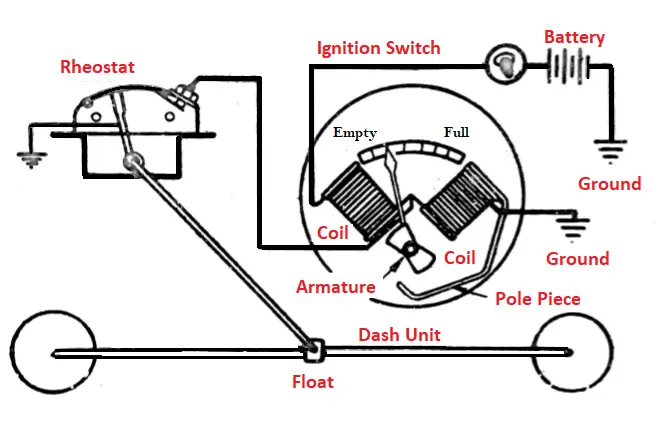
When the tank is full and the float is up, the resistance in the tank unit is high. The current flowing through the E (empty) coil also flows through the F (full) coil. Thus the armature is pulled to the right so that the pointer indicates on the F (full) side of the dial.
When the tank begins to empty, the float goes down and the resistance of the unit drops. Thus, more of the current flowing through the E coil passes through the tank unit. Since less current is flowing through the F coil, its magnetic field is weaker and the armature is pulled to the left so that the pointer indicates the E (empty side of the dial).
The fuel gauge operates only when the ignition switch is turned on. The current consumption of the gauge is so low (0.15 amp) as to cause no appreciable drain on the electric system.
Vibrations in voltage depend supplied to the gauge do not affect their accuracy as their operation depends upon the proportion of electric current flows through the coils of the dash unit, rather than on the actual strength of their magnetic fields.
The construction of the fuel gauge depends upon the tank. For small tanks, the movable contact is actuated directly by the float arm. The float may be either single or double. For large tanks, the movable contact may be mounted on a vertical axis and driven from the float arm by bevel gears.
Read Also: What are the Different Types of Lubrication Systems?
#2 Bimetal-Type Electric Fuel Gauge
The figure shows a bimetal-type electric fuel gauge. It also consists of two nits-the the sender unit and the dash unit or receiver unit. The sender unit is placed in the fuel tank.
These types of fuel gauge consist of a heating coil wound around a bimetal strip and on an external float mechanism which acts through a cam and flexible diaphragm so that the position of the float varies the height of earthed contact which in turn varies the tension in the bimetal strip.
The receiver unit is located on the instrument panel in front of the driver. The two units are connected by a wire and receiver current from the battery of the generator.
Working
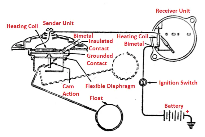
When the fuel tank is empty, the float is down and the two contacts in the sender unit are just touching. In this position, when the ignition switch is turned on, the current flows through the circuit, and heat is generated in the heating coil causing the bimetal to bend. As soon as the bimetal bends it opens the contact and the circuit breaks.
Then the heating coil and bimetal cool and the spring returns to its former position where contact is again made. Since the heating coils of the sender and receiver units are connected in series, similar slight bending of the bimetal in the receiver unit takes place, which pulls the pointer to the zero position of the receiver unit.
When the fuel tank is full, the float is up, and the eccentric shaft raises the earthed contact against the insulated bimetal contact, bending the bimetal in the sender unit. As the bimetal is under tension, more current is required to heat it so as to bend sufficiently to break contact.
Due to the increased current, a similarly increased bending of the bimetal in the receiver unit occurs which pulls the pointer to the “full” position. The cycle of opening and closing of the contacts is continuously repeated.
Read Also: 25 Car Dashboard Warning Lights and Indicators [Explained] PDF
#3 Thermal-Type Electric Fuel Gauge
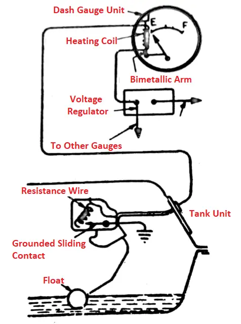
The figure shows a thermal-type electric fuel gauge. These types of fuel gauge consist of two unit-dash and a tank unit. The dash unit is exactly like the receiver unit of the bimetal electric fuel gauge.
The tank unit consists of a rheostat in the form of a sliding contact on a resistance wire, which is moved by the float. The two units are connected in series to a contact voltage regulator, which is energized when the ignition switch is turned on.
Working
When the fuel tank is full and the float is up the circuit has the least resistance in the tank unit resistance wire and more current flows through the circuit. This causes heating of the bimetal arm so that it bends the moves the needle towards a “full” position.
When the tanks begin to empty, the float drops. It increases the resistance which reduces the current to a value that causes the bimetal arm to force the needle towards an “empty” position.
Read Also: How does an Ignition Distributor System work? [PDF]
#4 Thermostatic Type Electric Fuel Gauge
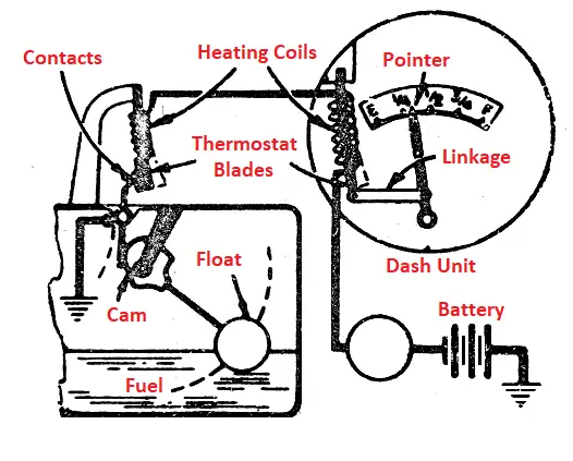
The figure shows a thermostatic type electric fuel gauge. It is an early type gauge still used on some late model cars. It uses two wires to connect the dash unit and tank unit, instead of one wire in other gauges. The dash unit consists of a pair of thermostat blades, each with a heating coil.
The coils are connected in series through the ignition switch to the battery. When the ignition switch is turned on, the current passing through the coils beats them. The heat causes the blades to bend so as to move an indicator over a scale. The tank unit consists of a float that actuates a cam. The cam, on turning, imposes bending on the tank thermostat blade.
Working
When the tank is full, and the float is up the cam puts a considerable bend in the blade. The current flowing through the heater coils, when the ignition switch is turned on, heats the tank blade, and it bends farther so that the contact separates. Then the blade cools and the points reopen.
This action continues as long as the ignition switch is on. Meanwhile, the blade in the dash unit is heated and bends the same amount. The movement of this blade is carried through linkage to the pointer which moves to indicate the “full” position.
When the tank is empty, the float is down, the cam bends the tank thermostat blade only a little. Thus, only a small amount of heating is enough to bend the blade farther and open the contacts. The dash unit blade bends only a little and the pointer indicates the “empty” position.
Conclusion
So now, we hope that we will clear all your doubts about Fuel Gauge. If you have still any doubts about “Types of Fuel Gauge” you can contact us or ask in the comments.
That’s it thanks for reading. If you like our article then please share it with your friends. If you have any questions about any topic you can ask in the comment section.
Subscribe to our newsletter to get notifications of our new posts.
Download PDF of this article:
Read Next:
Hi,
Thanks so much for explanations. I intend to rework my Bimétal electric gauge which inside coil wire is broken. Do you know usual wire diameter for this kind of coil. I expect 0,1mm.
Thanks for reply
Philippe.
You’re welcome.