In this post, you will learn what is a resistor? its symbols, selection of resistors, applications, and types of resistor are explained with diagrams. You can also download the PDF file at the end of this article.
The Resistor and It’s Types
Basically, electronic components are classified into active components and passive components. The components that supply the energy to the circuit are called active components.
Ex: Battery semiconductor devices etc.
In a reverse manner, the passive components are those which consume the energy from the source, either in the form of a drop or in the form of stored energy.
Ex: Resistors, Capacitors, Inductors, etc.
The passive components are used to limit the circuit current, vary the current or voltage in an electrical circuit. Depending upon their construction and working principle the applications of these components vary.
Resistors
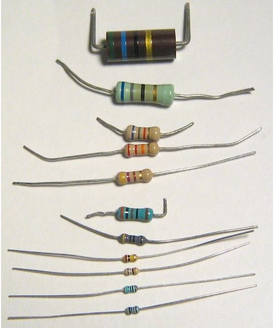
A resistor is an electrical/electronic passive component used to limit the flow of current. The figure represents the various types of resistors.
Specification of Resistors:
The specification of resistors are :
- Resistance value
- Tolerance
- Power rating
- Thermal stability
1) Resistance value (Ohmic value):
The magnitude of the resistor is been expressed in terms of its resistance value. The resistance value decides the quantity of current flow to be opposed. Thus the resistance value is expressed in ohms (Ω) or kilo-ohms (KΩ) or mega-ohms (MΩ). The resistance value is either printed on the surface of a resistor or by color bands.
2) Tolerance:
Tolerance represents the maximum and minimum values of a resistance value. It is specified in terms of percentage. It is been expressed as either ±% on the surface of the resistor or with the help of a fourth color band.
3) Power Rating (Wattage rating):
Power rating specifies the maximum power in watts that the resistor can handle without being destroyed or damaged. It also represents the power dissipation in the resistor in terms of I2R loss (or heat).
4) Thermal Stability:
Thermal stability indicates the stability in the resistance value to a maximum specified temperature. or It is the ability of a resistor to maintain the same resistance value with variation in temperature.
Types of Resistor and their Symbols:
Based on their operation following are the types of resistor:
- Fixed resistor
- Wire Wound Resistors
- Power type wire wound resistor
- Precision type wire-wound resistor
- Carbon Composition Resistors
- Cracked Carbon Resistors or Carbon Film Resistors
- Metal Oxide Resistors
- Metal Film Resistors
- Wire Wound Resistors
- Variable resistor
- Continuously variable resistors
- Potentiometers
- Rheostats
- Adjustable or pre-set resistors
- Decade resistance boxes
- Thermistors
- Varistors.
- Continuously variable resistors
- Tapped resistors
Read Also: 30 Different Types of Pliers: How To Use Them? [Explained with PDF]
1) Fixed Resistors

In these types of resistor, whose resistance value cannot be changed are called fixed resistors. Based on the construction and material used, fixed resistors are further classified into:
- Wire Wound Resistors
- Carbon Composition Resistors
- Cracked Carbon Resistors or Carbon Film Resistors
- Metal Oxide Resistors
- Metal Film Resistors
a) Wire Wound Resistors:
As the name itself indicates that these types of resistor are manufactured by winding resistance wire over a rod or tube. There are two types such as power type and precision type.
i) Power Type Wire Wound Resistor:
Power type wire wound resistor is manufactured by winding resistance wire made of nichrome or manganin or constantan and annealed at high temperature to limit the mechanical strain over a ceramic rod as shown in the figure.

To avoid short-circuiting between the turns the wire is coated with a thin insulation coating. The two ends of the wire are soldered to tinned alloy terminals for external connection. The whole assembly is coated with enamel.
The drawback of a power type resistor is, it is not applicable above 200 kHz frequency because inductance and capacitance effect will exist at high frequencies. So for high-frequency applications precision type wire wound resistors are used.
ii) Precision type wire-wound resistor:
These types of resistors are used above 200 kHz and are manufactured using two techniques such as ‘π’ technique and the Bi-fular technique.
Pi-technique (π Technique):

In this technique, even sections are made in a ceramic tube and the resistance wire made of manganin is wound in the clockwise direction (1, 3 sections) as well as in anticlockwise direction (2, 4 sections) alternately to avoid the inductive effect. The entire unit is coated with vitreous enamel.
Bi-fular technique:
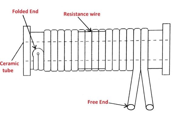
In this technique, the whole length of manganin wire is folded to half, and the folded end is fixed to one end of a ceramic tube. The wire is wound in one direction. This wire is provided with insulation coating to avoid short circuits.
Applications:
- Power type resistors are used in power supplies and control circuits.
- Precision type resistors are used in T.V. receivers, voltmeters, multimeters etc.
b) Carbon composition resistors:
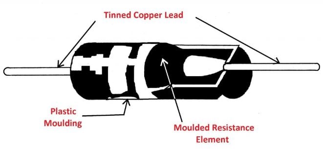
- The mixture of fine powder of graphite lac and resin as a binder is moulded into rods.
- These rods are baked in hydrogen 1400°C and copper leads are attached.
- The whole assembly is provided with a varnish coating and colour bands.
Applications: These are used in electronic circuits and in low-power amplifiers.
c) Cracked carbon or carbon film resistors:
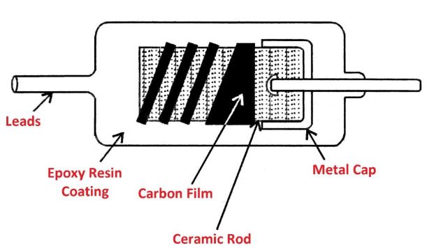
- These are high stability carbon resistor.
- Make the paste of calcinated ceramic powder with water. Make rods from this paste.
- Bake them at 1100° C and pass hydrocarbon gas with some percentage of nitrogen gas to form carbon film on rods.
- Fix metal caps to the ends of rods and connect copper leads. Provide spiralling on the surface and coat the resin.
Applications: These are used in,
- Computers
- Amplifiers
- Telephone
- T.V. circuits
d) Metal oxide:
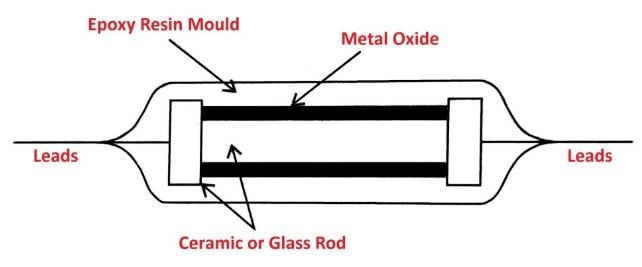
- Oxides of tin and antimony are sprayed over the ceramic rod at 1200° C.
- Metal caps are attached to the ends and copper leads are connected to it.
- Resin coating is provided on the surface with colour bands.
e) Metal film resistors:
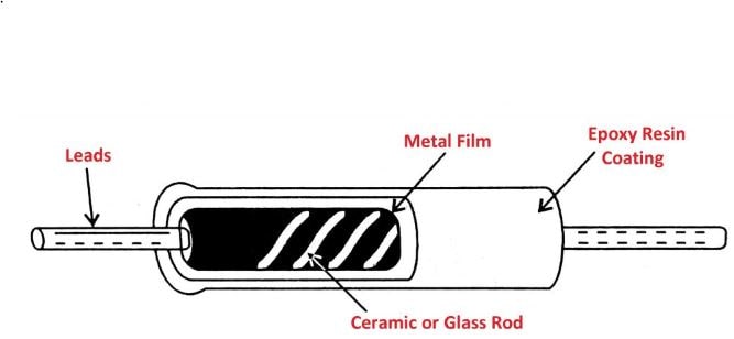
- The rods of ceramic maintained at 300°C are kept in an evacuated chamber that contains an alloy of nickel-chromium.
- Pass current through this alloy, so the vapours of nichrome are deposited on the surface of the rod, which gives a thin coating of nichrome.
- Connect the copper leads and coat the resin with colour bands.
Applications:
- These are used in high-frequency test and measuring instruments.
- Used in high-frequency amplifiers.
2) Variable resistors:

These are types of resistor, whose value can be varied either continuously or in steps are called a variable resistor.
Based on the operation, these are classified into :
- Continuously variable resistors :
- Potentiometers
- Rheostats
- Adjustable or pre-set resistors
- Decade resistance boxes
- Thermistors
- Varistors.
a) Continuously variable resistors:
i) Potentiometers (Pot):
These are continuously variable resistors used as voltage dividers in electrical and electronic circuits. Potentiometers are of carbon film and wire-wound types.
Carbon Film Potentiometers:
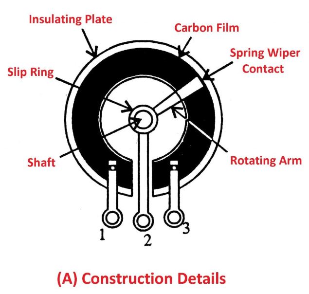
- This is used in low power circuits.
- The constructional details are shown in the figure.
- The mixture of carbon powder and resin is coated on a circular ring plate of insulating material. Two leads are connected to the ends of the ring called as fixed terminals (1&3).
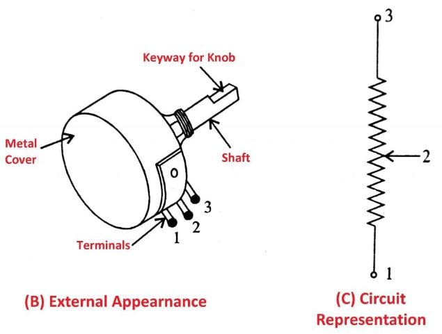
- The variable terminal (2) is fixed to the moving arm (rotating arm) which is connected to the shaft at one end and wiper made of brass at other ends.
- The whole unit is enclosed in a metal casing.
Applications: These are used :
- In radios, Amplifiers and T.V. sets.
- To control volume and tone, in radio and T.V. etc.
- To control brightness and contrast in T.V. sets.
Carbon film potentiometers are further classified into linear and logarithmic potentiometers.
Linear potentiometer: In these potentiometers, the resistance value is varied linear i.e. its value remains the same throughout.
Logarithmic potentiometer: In these potentiometers, the resistance value is not linear i.e. at one end it changes gradually, and at other ends, it changes drastically.
Wire Wound Potentiometers:

- Constructional details of wire wound potentiometer are shown in the figure.
- The nichrome wire is wound on asbesta cement or ceramic ring. The two ends of the ring are connected to fixed terminal 1 & 3.

- The variable terminal (2) is connected to moving arm and the rotating shaft, through a slip ring to wiper over the wire from one end to the other. Applications remain the same as the carbon film potentiometers.
ii) Rheostats:
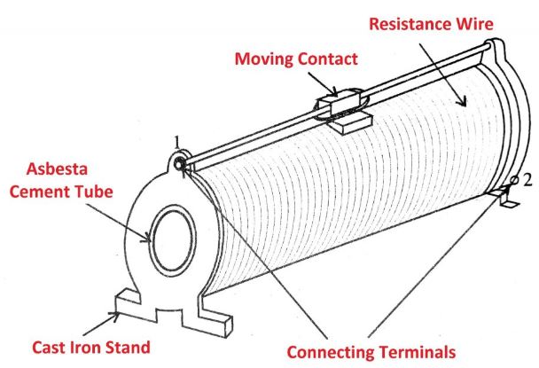
- A rheostat is a variable wire wound resistor, connected in series with the load to limit the flow of current.
- The constructional details are as shown in the figure.
- The nichrome wire is wound firmly over a ceramic or cement tube. The two ends of the wire are connected to 2 connecting terminals. (1 and 2).
- The resistance value can be varied by sliding contact that moves on the wire.
Applications: These are used:
- In electrical and electronic circuits to limit the current.
- Used as a resistive load.
- In laboratories, because of their small ranges of resistance values (10Ω-100Ω)
b) Adjustable or Preset resistors:
i) Decade Resistance Box (DRB):
- Decade resistance box is an adjustable resistor, whose resistance value can be varied in steps.
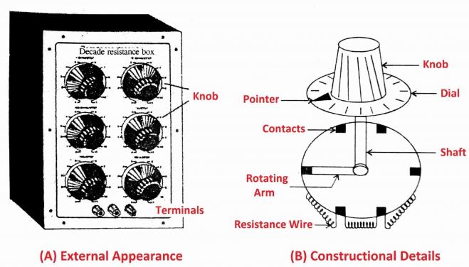
- The constructional details are shown in the figure which consists of 3 to 6 sections made of carbon resistors.
- The resistance of each section is varied in steps by selector switches fixed to dials.
Applications:
- It is used as test equipment and calibration equipment for multimeter carlibration.
- It is also used in laboratories for conduction of experiments.
ii) Thermistors:
- Thermistors are thermally sensitive resistors, i.e. the resistance value varies with increasing temperature.

- If resistance value decreases with an increase in temperature, then such thermistors are known as negative temperature coefficient (NTC) thermistors.
- In positive temperature coefficient (PTC) thermistors, the resistance value increases with increase in temperature.
- The oxides of nickel manganese copper are mixed with binder and rods or discs are formed. e) These rods or discs are heated at 1200° C. The silver is sprayed over the surface, leads are soldered to silver contacts and resin, the coating is provided for external protection.
Applications:
These are used,
- For measurement of temperature, thermal conductivity, wind velocity etc.
- Switching devices that are temperature-activated.
- In time delay relays and thermal relays.
- In voltage regulators.
c) Varistors (VDR):
- A varistor is a voltage-sensitive resistor, i.e. its resistance value varies with change in applied voltage. It is also called a voltage-dependent resistor.

- These are manufactured by mixing silicon or carbide, metal oxide (zinc oxide + bismuth) with a ceramic binder. Then it is pressed into discs or rods and heat-treated at 1200°C in a controlled atmosphere.
- The leads are connected to the ends and the entire unit is placed in a ceramic body.
Applications:
These are used,
- As sensing element, in voltage stabilizer of T.V. and motor control circuits etc.
- In switch circuits, relays etc.
- To protect the components from inductive surge voltages
3) Tapped resistors:
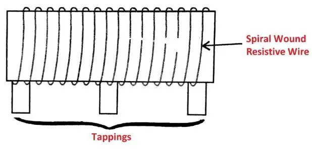
- The resistor in which the resistance value can be tapped at fixed length is called as a tapped resistor.
- this types of resistor consist of firmly wound resistance wire on a ceramic rod. The tappings are provided on the wire at a fixed length.
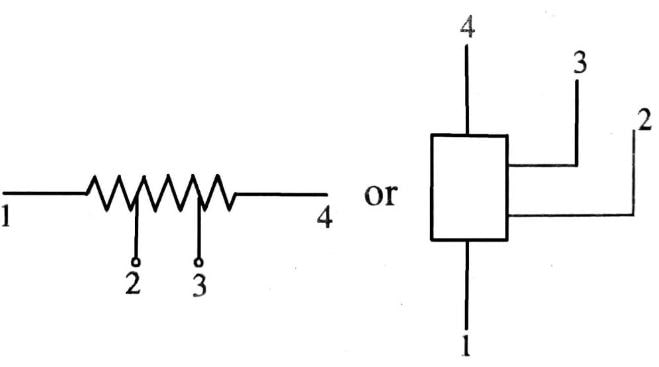
Applications: Used in fan regulators to get variable speed.
Light Dependent Resistor (LDR):
Length dependent resistor is a bipolar semiconductor resistor, whose resistance value depends on the intensity of incident light. i.e. when LDR is exposed to light its resistance value decreases and when it is not illuminated its resistance value is very high (100 kΩ or more). This higher value of resistance of LDR has known a dark resistance.

LDR is manufactured by depositing a thin film of cadmium sulphide or cadmium selenide on a ceramic substrate. The leads of tin or indium are soldered to the ends of the deposited layer. The thin layer is formed in a zig-zag fashion to increase the length and hence the resistance value. The window is fixed on the layer to allow light to fall on a thin layer of cadmium sulphide.
Resistance Colour Coding:
Resistors are manufactured in different sizes and shapes. If they are of big size then it is possible to print their values on the surface of resistors themselves. But if they are of small size then, it is difficult to print the values. So the Electronic Industries Association (EIA) has adopted the Standard Colour Coding method to indicate the resistance value.
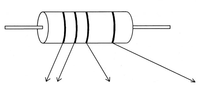
In this method, the different color bands are printed on the left end of the body of the resistor to indicate the numerical values. The color code chart is given in table (A). To identify the resistance value the following steps are adopted.
- Hold the resistor so that colour bands should start from the left-hand side
- Read the colour bands from left to right.
- The first band shows the first digit of the resistance value.
- The second hand indicates the second digit, the third band indicates the multiplier or number of zeroes to be added after the second digit.
- The fourth band indicates the tolerance in percentage.
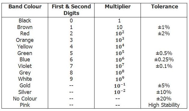
Ex: Write color code for the following resistors:
Ans: i) 1KΩ 10% tolerance: Brown Black Red Silver
ii) 3.3KΩ 5%: Orange Red Gold
Resistance Letter Code (BS 1852 Code) Method:
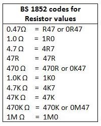
Generally, on larger power resistors, the resistance value, tolerance, and even the power rating are written on the body of the resistor rather than color code. But when the component is dirty, it is difficult to read the position of a decimal point or comma, so to overcome this misread British Standard BS 1852 Standard coding system is used.
This method decimal point position is replaced by the suffix letters “K” for thousands or kiloohms, the letter “M” for millions of megaohms, and for both multiplier is denoted by letter “R” when the multiplier is equal to or less than 1. Any number coming after R is equivalent to a decimal point.
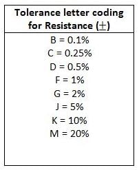
Sometimes after the resistance value, an additional letter is used, which represents the tolerance of the resistor. The BS 1852 letter code and tolerance letter coding for resistors are shown below:
Applications of Resistor:
Resistors are used as:
- Electrical load
- Current limiter
- Voltage divider
- Biasing element
- Filter with capacitor
- Relay coil in thermal relays than
- Volume, tone, brightness & contrast controller in radio and T.V. sets etc.
Conclusion
Thank you for reading. That’s it. If you have any questions on “Types of Resistor” tell us in the comments. Share this information with your friends.
Want free PDFs sitting at home? Then subscribe to our newsletter.
Download PDF of this article:
You might like to read more in our blog:
Please can you send the the PDF
regards
Andrew
The PDF file has been sent to your inbox.
I LOVE YOU, for this beautiful work.
Thanks for your feedback.
Awesome stuff
Thank you so much.
Pls send me the pdf
The PDF file has been sent to your inbox.
Please, I need to get the PDF file.
The PDF file has been sent to your inbox.
May I receive a copy of the pdf, please.
The PDF file has been sent to your inbox.
Thanks for sharing knowledge.
You’re welcome.
Please send me pdf file
The PDF file has been sent to your inbox.
Please send me a PDF file
The PDF file has been sent to your inbox.
Nice content. A link may b given for converting to pdf form and for downloading .
Thanks for reading. I just updated the article with the PDF file, now you can download it.
Thank you sir.
I’m get a new knowledge in your it’s post.
And I have yet some knowledge about electrical engineering components.
I’m glad you found it helpful. You’re most welcome.
Nice content
Thank you 🙂