In this article, you’ll learn about the different types of inductors and their applications are all explained with examples and applications.
Also, download the PDF file at the bottom of this article.
What is Inductor?
Inductors are electrical/electronic component that opposes a change in current due to its self-inductance. It consists of a number of turns of fine wire of copper wound on a core of some material (air, iron, powdered iron, or ferrite material) in spiral form.

When the current flows through a coil of inductor it induces EMF due to the effect of electromagnetic induction which opposes the change in the cause for it (applied current). Inductors are mainly classified depending on the core material used and operating frequency.
Read also: Types of circuits, Kirchhoff’s Law and Its Classification
Types of Inductors
Following are the types of inductors:
- Iron Cored Inductors
- Air Cored Inductors
- Powdered Iron Cored Inductors
- Ferrite Cored Inductors
- Variable Inductors
- Audio Frequency Inductors
- Radio Frequency Inductors
- Multi-layer inductor
- Molded inductor
- Coupled inductor
- Thin film inductor
- Colour ring inductor
Read Also: Types of Circuit Breakers: Their Working & Applications [PDF]
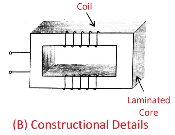
#1 Iron Cored Inductors
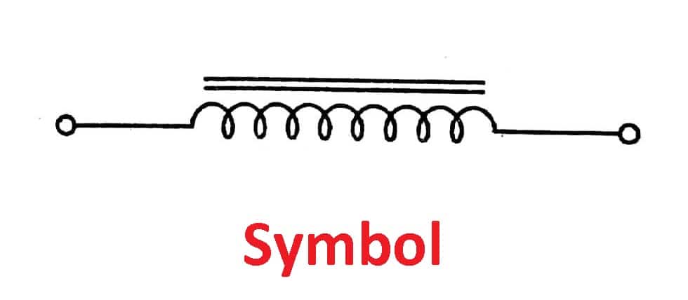
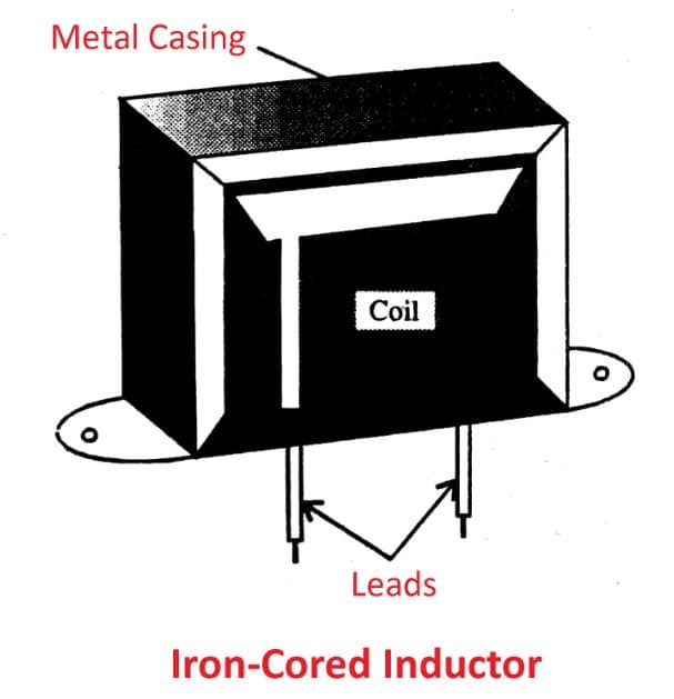
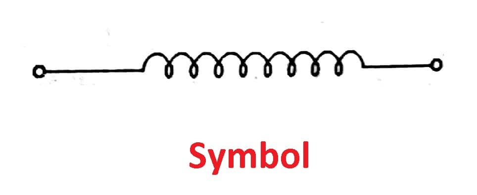
The figure represents the constructional details and symbol of an iron-cored inductor which consists of a coil wound on laminated iron core or cobalt or nickel alloys.
Two lead are connected to two ends of the coil and is also center-tapped to half of the length of the coil. It is also known as a transformer that consists of primary and secondary windings in which two leads are soldered to primary and three
Applications: These are used:
- At low power frequency (50Hz) for building surge voltages.
- At audio frequency (20Hz – 20kHz) as AF chokes for tone control.
- As filter chokes with the capacitor in power supplies.
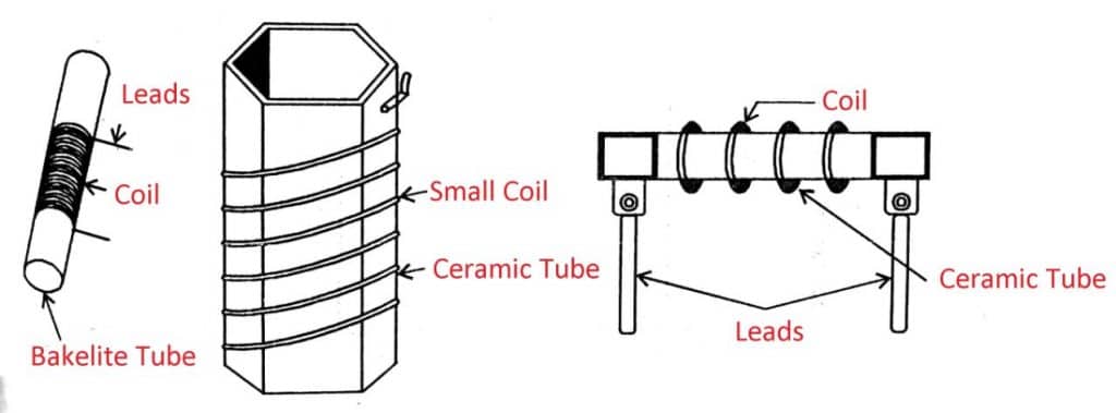
#2 Air Cored Inductors

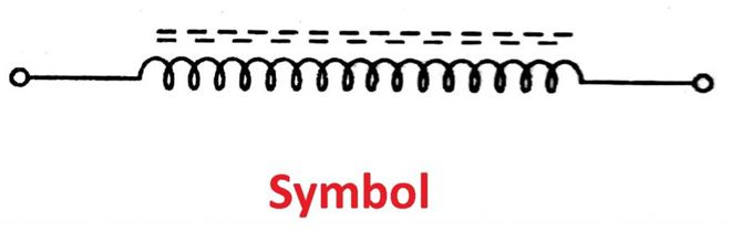
The figure represents the constructional details of air-cored inductors, which consist of air as core material, i.e., coil is wound on an insulating Bobin that contains air. These can be operated at radio frequencies.
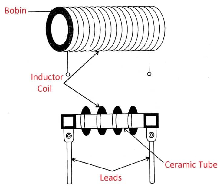
Applications: These are used:
- As RF chokes, RF transformers and IF transformers
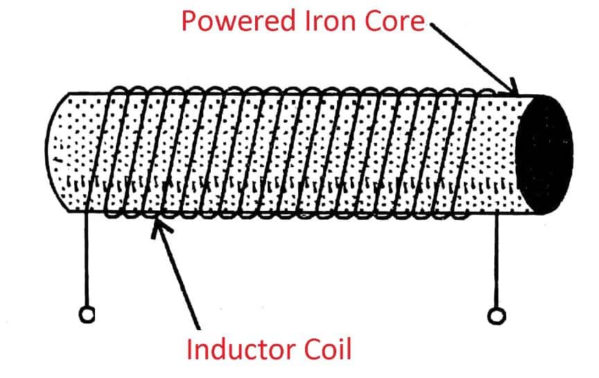
#3 Powdered Iron Cored Inductors
Constructional details of the powdered iron cored inductor are shown in the figure, in which powdered iron rods are used as cores. These are used at higher frequencies.
Applications: These are used:
- RF chokes, RF transformers in radio receivers.
- As IF transformers and IF chokes in radio receivers.
- As an arial coil in tuned circuits of radio receivers.
- For tuning radio connected with gang condensers.
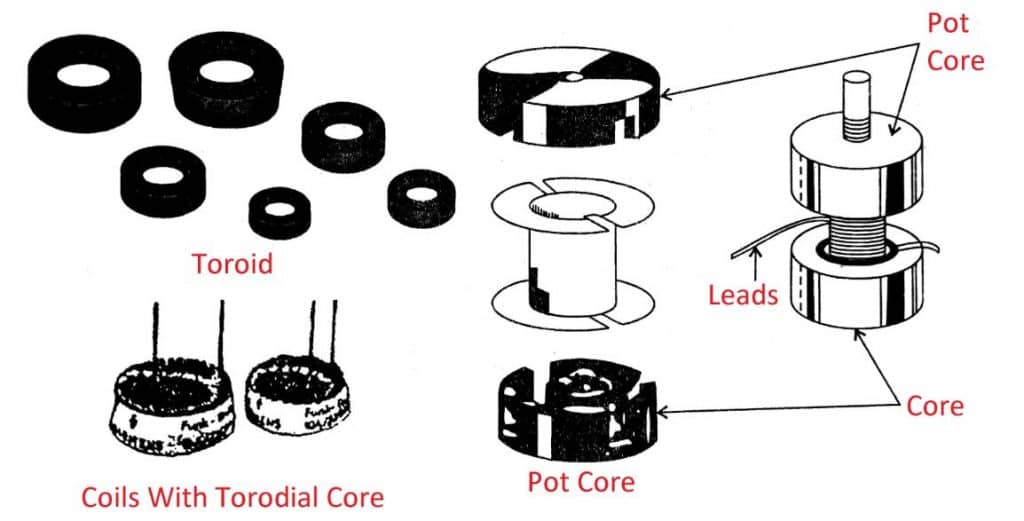
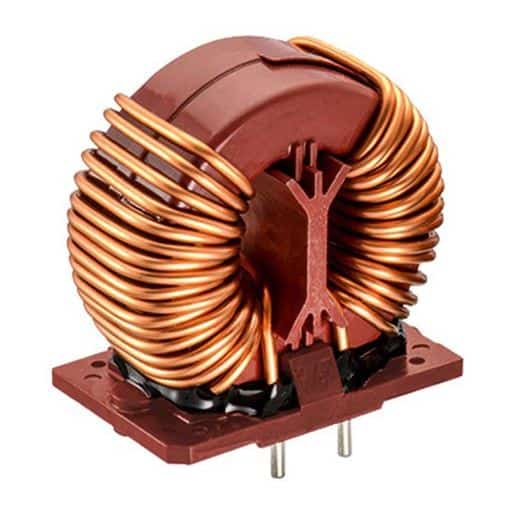
#4 Ferrite Cored Inductors
Ferrite-cored inductors contain coils wound on a solid core made of ferrite material. These are pot core and toroidal core type inductors, as shown in the figure.
Applications: These are used at higher frequency ranges.
- For radio interference suppression.
- As filter chokes.
- For colour T.V. raster generation.
#5 Variable Inductors
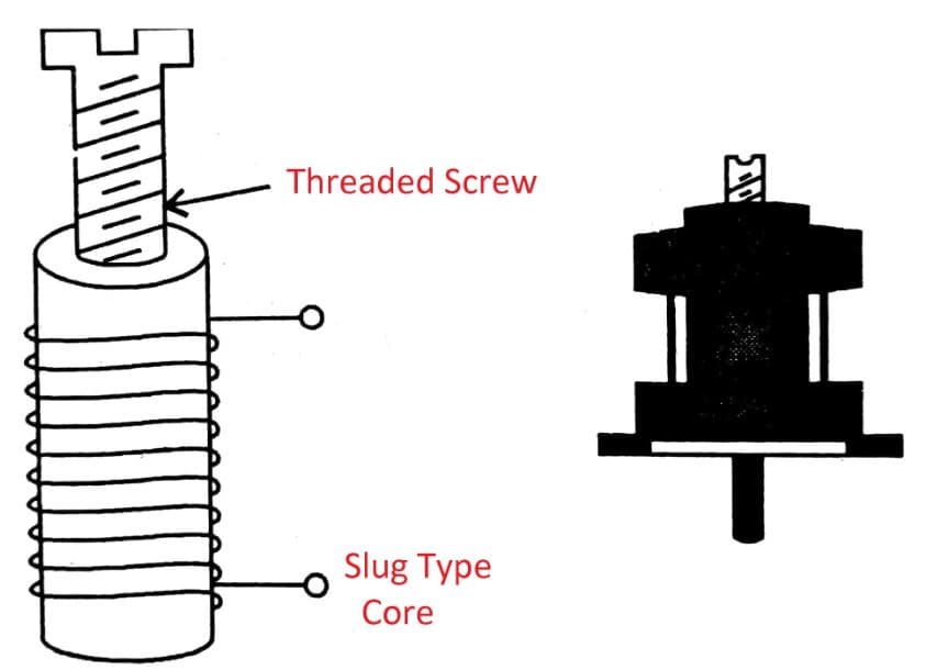
The inductors whose inductance value can be varied continuously are known as variable inductors. The constructional details are shown in the figure. Here threaded screw is used as a screw, which can be rotated in or out of the coil to vary the inductance value.
Applications: These are used,
- Tuning circuits
- Coupling circuits
- Oscillator circuits
- Timing circuits
Read Also: Different Types of Electrician Tools and Their Uses [Pictures]
#6 Audio Frequency (A.F.) Inductors (AF Chokes)

Choke is an inductor that opposes a change in current. If the choke operates at an audio frequency range, then it is called an A.F. choke or A.F. inductor.
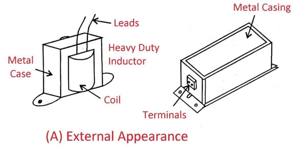
It contains a number of turns of thin wire wound on a laminated iron core as shown in the figure.
The wire is made up of insulated copper, and the unit is placed in a metal casing.
Applications: AF chokes are used,
- As filter chokes in radio and T.V. receivers.
- For generating voltage surges in fluorescent lamp sets.
- In tube light sets.
#7 Radio Frequency (R.F.) Inductors (R.F. Chokes)
These are designed to operate at the radio frequency range (>20 kHz), as shown in the figure.
They consist of a number of turns of thin wire wounds on an insulator tube or powdered iron core. For higher permeability, powdered iron cored is used.
Applications: These are used:
- Inductors are used.
- In radio transmitters.
#8 Multi-layer inductor
Multi-layer inductors consist of several layers of wire wound on top of each other. A multilayer inductor has a first conductive coil pattern and a second conductive coil pattern arranged in two layers at the top.
These are electrically connected in series to 2 consecutive more conductive coil patterns disposed of at the bottom. This inductor usually has a large inductance due to the more number of turns of the winding.
These inductors can be used in mobile communication systems. They are used in applications that require noise suppression at high frequency and impedance matching.
Advantages
- By delivering lower operating frequencies, it can achieve higher inductance results.
- In addition, the capacitance between the wires also increases.
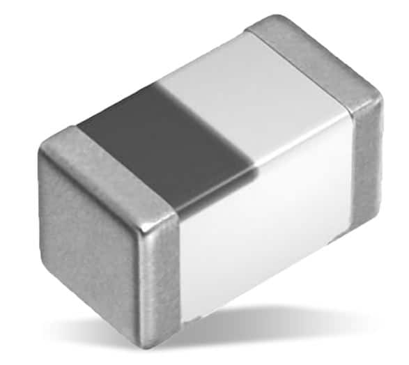
#9 Molded Inductor
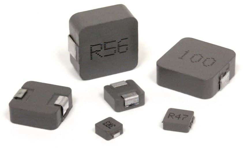
These are manufactured by compressing the magnetic material into a mold using a polymer around a conducting air coil to form its structure. Molded inductors are commonly made of plastic or ceramic, while the core is made of ferrite or phenolic material.
The windings of this inductor can be of various designs. These are available in different shapes, such as axial, cylindrical, and bar shapes. Due to their miniature size and lightweight, they can be used in PCBs (Printed Circuit Boards), mobile devices and computers, etc.
Advantages
- These inductors have high DC bias and saturation current.
- The frequency range of this inductor is up to 5 MHZ.
- It has less self-induced electromagnetic interference.
#10 Coupled Inductor
The coupled inductor consists of two windings around its core. The changing magnetic flux due to the first winding induces an EMF in the second winding, known as mutual inductance. These windings are electrically isolated, providing electrical isolation between the two circuits. The coupled inductor is also known as a transformer.
Coupled inductors are used in various applications depending on their windings. 1:1 winding ratio inductors are for increasing electrical isolation or series inductance. 1:N coupled inductors are used in other energy conversion circuits such as flyback, sepic, zeta, etc.
Read Also: Types of Batteries: Their Advantages & Disadvantages [PDF]
#11 Thin Film Inductor
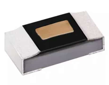
A thin film inductor consists of several spiral-shaped thin film coils placed on a substrate, which facilitates the induction process. These are designed on a substrate of thin ferrite or magnetic material.
The thin film allows for better electrical stability and resistance to vibration due to the lower height. Thin film inductors have high accuracy and performance and are compact. They are commonly used in mobile communication devices, wireless networks, power supplies, etc.
Advantages
- This inductor has a high Q or quality factor, which means less energy loss.
- It has high accuracy and also high performance.
#12 Colour Ring Inductor
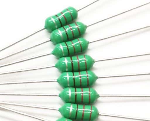
An inductor of this type is made by wrapping thin copper wire around a dumbbell-shaped ferrite core and connecting two lids at the top and bottom. When an unstable current is passed through it, it produces a transfer magnetic field, and this magnetic field affects the current.
The inductor goes through a molding process where the values are printed as colored bands, so just like a resistor, the value is determined by comparing the bands with a color code chart. These inductors are used in line filters, filter designs, and boost converters.
Read also: What are different types of AC motors?
Specification of Inductors
The specifications of inductors are:
- Inductance value
- Resistance
- Capacitance
- Frequency range
- Quality factor
- Power loss
- Current rating
- Temperature coefficient
1) Inductance value:
The value of inductance is measured in terms of its inductance value and is expressed in henries, millihenries, and microhenries.
2) Resistance:
Resistance is the ohm value of an inductor wire, which is expressed in ohms.
3) Capacitance:
The stray capacitance effect exists in an inductor, i.e., a coil has some capacitance between windings called a stray capacitance. It lies between 1 to 10pF.
4) Frequency range:
The frequency range is the maximum frequency up to which the inductor can work safely.
5) Quality factor:
The reciprocal of the power factor is the quality factor. It is the ratio of inductive reactance (XL) to the resistance (R) of the coil. It is merely a number. For a good coil, Q must be high, and R must be below.
i.e., Q-factor=XL/R
6) Power loss:
The loss in the coil is due to the copper wire, stray capacitance, and resistance of the coil. The less the power loss greater will be the quality of the coil.
7) Current rating:
The current rating is the operating current of an inductor, and it is measured in Amps.
8) Temperature coefficient:
The temperature coefficient represents the stability in inductance value with a temperature change. It is expressed in ppm/°c.
Read Also: What are the different types of electric motors? [PDF]
Inductance Colour Coding
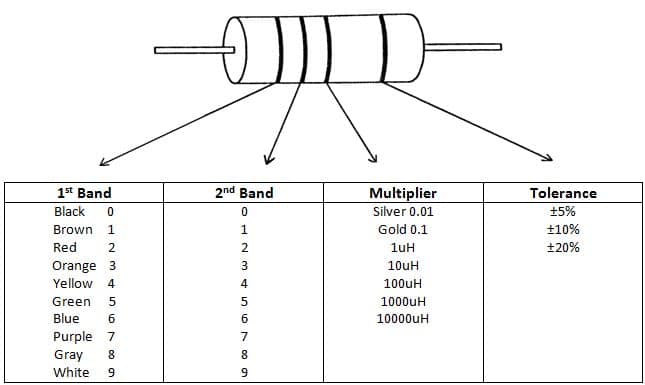
According to the EIA standard, the color code table for the inductor is given below. To identify the value of the inductor, the following steps are used:
Hold the inductor so that color bands should start from the left-hand side. Read the bands from left to right.
The first band indicates the first digit, the second band indicates the second digit, the third band indicates the multiplier or number of zeroes to be added after the second digit, and the fourth band indicates the tolerance in percentage.
Read Also: What are the Different Types of Fits Used in Metrology?
Factor Influencing the Inductance of an Inductor
The inductance of an inductor is,
- Is directly proportional to the square of the number of turns (N2) of the coil.
- Directly proportional the area (A) enclosed by each turn.
- Directly proportional to the permeability of the core (µa).
- Inversely proportional to the length (l) of the coil.
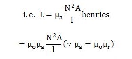
Where,
- µa = Absolute Permeability of the core material
- µo = Absolute Permeability of air
- = 4π(Pi)x10^-7 H/m
- µr = Relative permeability of the core material
Read also: Types of DC motors Explained with diagrams (PDF)
Applications of Inductors
Inductors are used in:
- Communication circuits
- Filter circuits
- Tuning circuits
- Magnetic amplifiers
- Fluorescent lamps
- Telemetric equipment
- Modulating and demodulation circuits
- Radar sets.
Closing It Up
That’s it, thanks for reading. If you have any questions about “types of inductors,” you can ask in the comments. Share this article if it is worth sharing.
Subscribe to our newsletter to get notifications of new articles.
Download the PDF from here:
Read Next:
- Capacitors: Definition, Types, Specifications, and Application of Capacitor
- How does an electronic Ignition System work? Its Advantages
- What are the different types of measuring tools?
More: