In this article, you’ll learn about horizontal boring machine. Its parts, types, tools and operations.
You can also download The PDF file of this article at the end.
In order to better assist you in understanding, we will go over every aspect of the horizontal boring machine in this article. Let’s begin by defining the horizontal boring machine.
What is a Horizontal Boring Machine?
The boring machine is one of the most versatile machine tools used to bore holes in large and heavy parts such as engine frames, steam engine cylinders, machine housing, etc.
Which are practically impossible to hold and rotate in an engine lathe or in a drill machine. Therefore, this is the main purpose for which the boring machine was developed.
In addition to its primary purpose of boring, the range of speeds and feeds provided to the various traversing parts allow drilling, milling, and facing to perform with equal facility.
By the fitting of simple attachments, the use of the machine can extend still further to include screw cutting, turning, planetary grinding, or gear cutting.
In types of boring machines, the horizontal boring machine is one of the most useful and important machines. Let’s first understand the parts of a horizontal boring machine before moving on to the different types of boring machines.
You might like to check this: Different Types of Cutting Tools & Their Uses
Parts Horizontal Boring Machine
In a horizontal boring machine, the work is supported on a table which is constant and the tool turns into a horizontal axis. A horizontal boring machine can perform boring, reaming, turning, threading, facing, milling, grooving, recessing, and many other operations with suitable tools.
Heavy, asymmetrical, and unbalanced workpieces can be easily held and machined in this machine. Different types of horizontal boring machines are designed to suit different purposes.
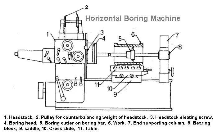
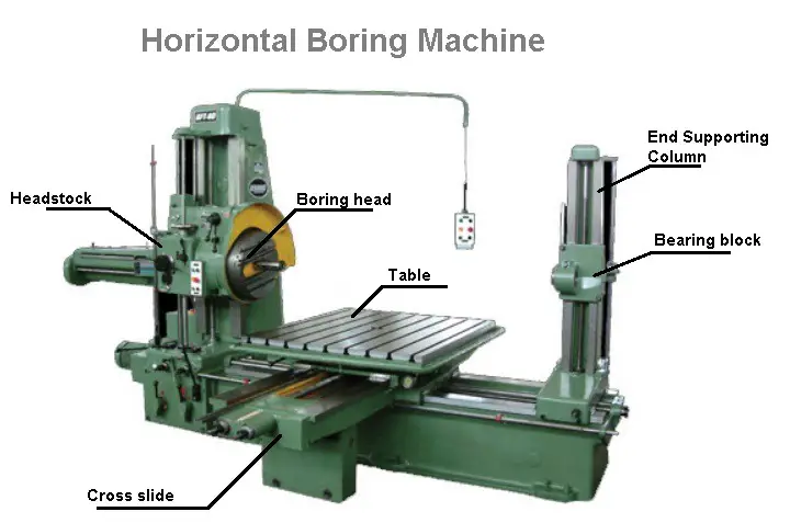
The following are the main parts of a horizontal boring machine:
- Bed
- Headstock supporting column
- End supporting column
- Headstock
- Saddle and table
- Boring bars
#1 Bed
- The bed is that part of the machine which is fitting on the floor of the shop and has a box-like casting.
- The bed supports the columns, tables, and other parts of the machine.
#2 Headstock Supporting Column
- The column provides support to the headstock and guides it up and down accurately by the guideways.
- The column has hollow houses and is heavily ribbed to add rigidity.
- Some columns are stationary, others may be made to slide along the bed.
#3 End Supporting Column
- The end supporting column is situated at the other end of the bed houses.
- A bearing block is provided for supporting a long boring bar.
- The column may be adjusted on the slideways of the bed towards or away from the spindle to support the different lengths of boring bars.
- It may be moved at right angles to the spindle as in the case of a floor-type machine.
#4 Headstock
- The headstock mounting on the column supports, drives, and feeds the tool.
- A spindle provides rotary movement to the tool and the quill may be moved longitudinally to provide feeding movement of the boring cutter.
- The spindle nose is provided with a tapered hole for receiving taper shanks of the boring bar or any other tool.
- A headstock may move up and down on the column to set the tool for different heights of the work.
#5 Saddle and Table
- The tables serve as work surfaces and have T-slots for holding various devices.
- The saddle allows the work to be moved longitudinally on the bed. The table may be moved crosswise on the saddle.
- These movements may be slow or rapid and are performed by hand or power.
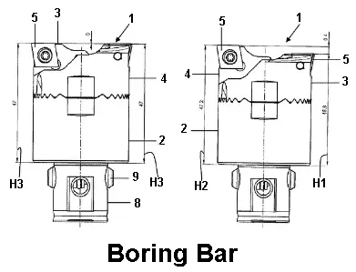
#6 Boring Bars
- The boring bar supports the cutter for holding operations on jobs having large bore diameters.
- For short holes, the bar may support the headstock spindle end only.
- For long work, the bar is supported on the spindle end and on the column-bearing block.
Now, lets discuss the different types of horizontal boring machines.
Read also: Everything You Need To Know About The Single Point Cutting Tool
Types of Horizontal Boring Machines
The following are the four types of horizontal boring machine:
- Table-type horizontal boring machine.
- Floor-type horizontal boring machine.
- Planner-type horizontal boring machine.
- Multiple heads type horizontal boring machine.
#1 Table Type Horizontal Boring Machine
The table types are the most common of all horizontal boring machines.
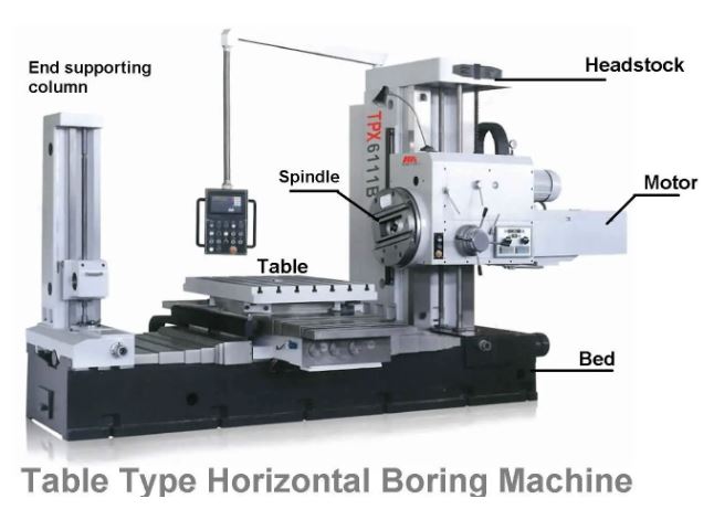
The name horizontal boring machine is given because the work is mounted on the table which is adjustable and feeds are given by hand or power, lengthwise or crosswise with respect to the bed of the machine.
The headstock may adjust vertically on the column and the spindle has a horizontal feed motion.
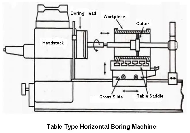
The machine essentially consists of a bed, headstock supporting column, end supporting column, headstock, saddle and table, and boring bar. The table, saddle, and headstock may be adjusted by leadscrews using micrometer dials.
This type of machine is appropriate for general-purpose tasks where it is necessary to carry out more operations in addition to boring.
#2 Floor Type Horizontal Boring Machine
The floor-type horizontal boring machine has notable uses a constant floor plate on which T-slots are provided to hold the work.
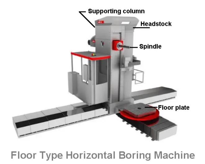
The headstock supporting column and the end supporting column are mounted on the runways which are placed at right angles to the spindle axis.
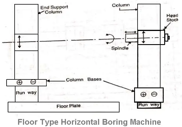
Thus any crosswise adjustment or cross-feed movement is provided by the spindle itself and not by the work.
This is designed for holding very large and heavy workpieces that are difficult to mount and adjust on a table.
#3 Planer Type Horizontal Boring Machine
The planer-type horizontal boring machine resembles the table type but the table slides directly on the bed instead of on a saddle angle to the spindle similar to a planer.
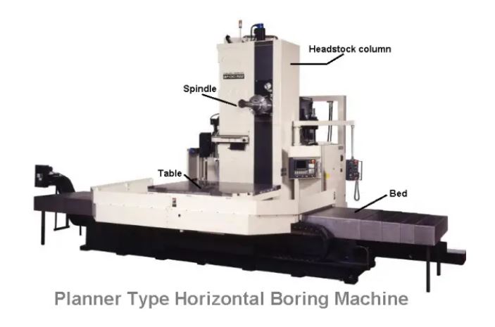
The end of the supporting column and headstock supporting column may adjust towards or away from the table to accommodate different widths of work.
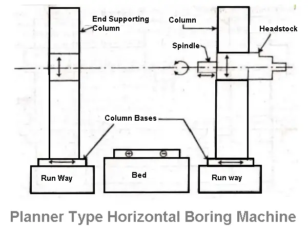
This type of machine is suitable for supporting a long work.
#4 Multiple Head Type Horizontal Boring Machine
The machine resembles a double housing planer or a Plano-miller. The table is supported by a long bed on which it reciprocates.
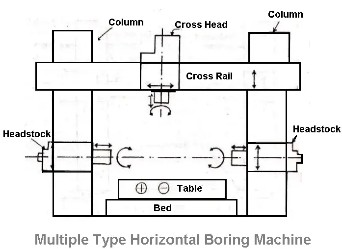
There are two vertical columns at two sides of the bed, nearly in the middle of the bed. The two columns are bridged by a cross rail.
The machine may have two, three, or four headstocks. This type of machine may be used as a horizontal and vertical machine.
The machining operations can be performed simultaneously at different work surfaces.
Read Also: Understand The Different Types of Chips In Metal Cutting
Size Of A Horizontal Boring Machine
The size of a horizontal boring machine is specified by the diameter of its spindle in mm. The diameter of the spindle varies from 75 to 355 mm.
To specify a boring machine other important dimensions such as spindle motor horsepower, column heights, size of the table or size of the floor plate, spindle speeds, feeds and length of feeds, floor space required, the weight of the machine, etc should also be stated.
Read also: What is Shaper Machine and The 4 Major Types of Shaper Machines
Boring Machine Mechanism
The machine contains different controls for the movements of the different parts of the machine. A table-type machine has the following movements:
- The headstock and the end supporting block may be moved up and down.
- The spindle may be rotating. The spindle has different speeds.
- A spindle may move in or out by hand or power for feeding.
- The saddle and the table may move by hand or power.
- The columns may move by hand or power.
All these movements may be given independently or in combination with two or more movements.
As all the controls are housed in a particular position of the machine the operator may give close attention to the work while controlling the machine.
Work Holding Devices For Horizontal Boring
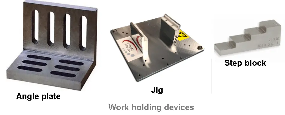
The work may be supported on the table by conventional work holding devices or by special fixtures.
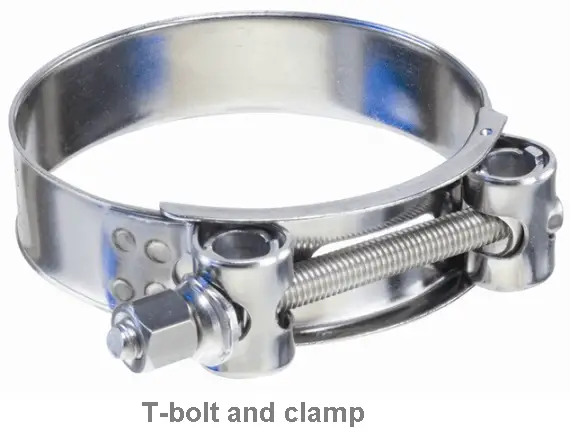
Conventional work-holding devices comprise T-bolts and clamps, angle plates, step blocks, etc. Special jigs are used in mass production work. The jigs locate the work and support and guide the boring bar.
Read Also: 12 Different Types Of CNC Machine [Complete Guide]
Horizontal Boring Machine Operations
In boring, the work remains stationary and the tool is rotated. Holes are bored by using boring bars. Multiple holes are bored one after another by changing the position of the workpiece aligning it each time with the boring bar.
To bore a hole, the boring bar is fitted to the spindle and the cutter is adjusted in the boring bar to the required dimension and a light cut is then taken. The bore is measured, the required speed and feeds adjusted and the cut is then completed.
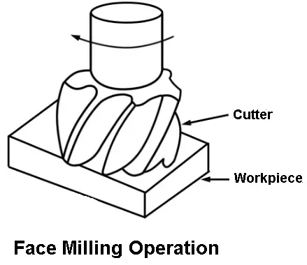
In a boring machine, for milling operation, any type of milling cutter may fit the spindle. A facing cutter is used for machining flat vertical surfaces.
For face milling operation, the tool or work may be fed to complete the cut. The end mill is used to produce grooves and slots. Is illustrated in face milling operation.
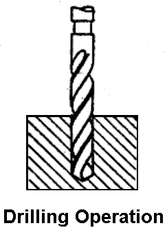
All other operations such as drilling reaming, counterboring, tapping, and spotfacing operations may perform similarly to boring operations. This is illustrated in the drilling operation.
Read Also: 9 Main Difference Between Up Milling and Down Milling
Boring Tool Mountings For Horizontal Boring
The different types of equipment for mounting cutters in horizontal boring machines are:
- Boring bar
- Boring head or cutter head
- Facing head
#1 Boring bar
Ordinary boring operations are carried out with tools mounted on a bar held in a spindle having a morse taper hole.
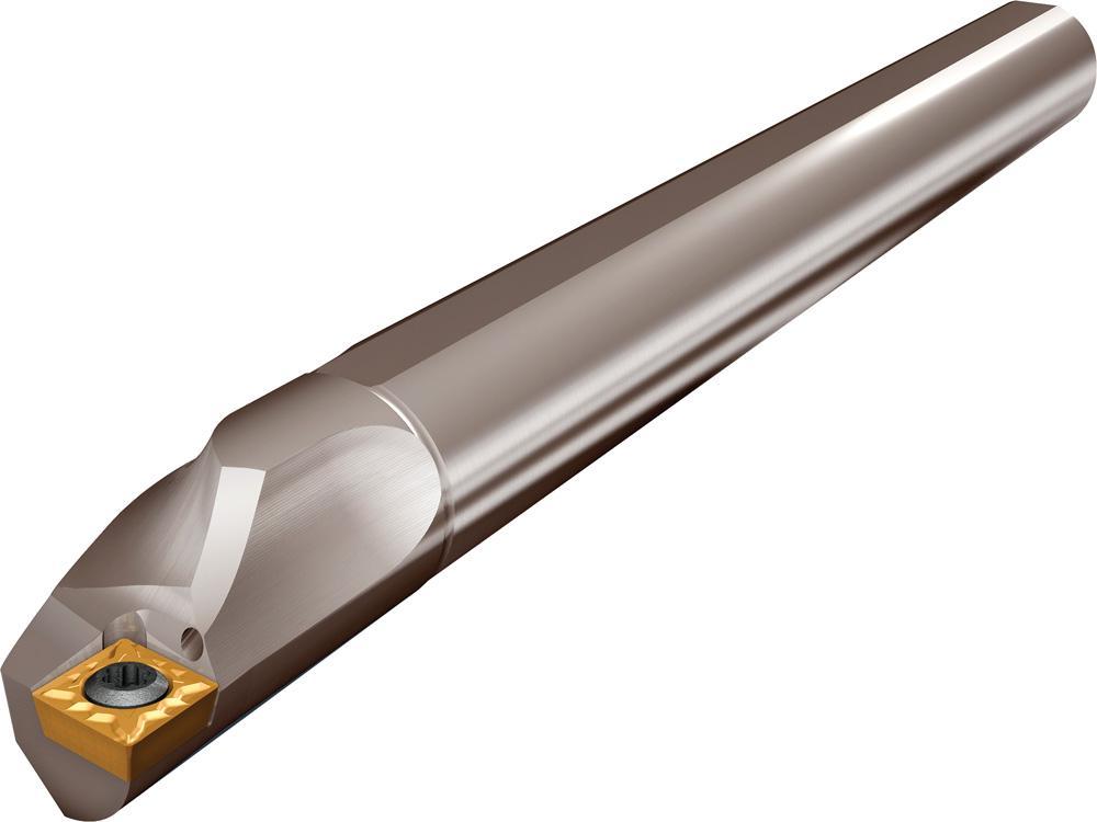
The maximum diameter of the bar employed is ordinarily not larger than the spindle diameter, and the length is such that it can reach the end column support.
A boring bar should be of the maximum diameter and minimum length to reduce bending or vibration and it may be supported in various ways to suit to different types of workpieces.
1.1 Methods of Supporting Boring Bars.
Supporting by Spindle
For boring blind holes, bars are using to support at the spindle end only. This type of bar is known as a stud bar.
Supported by the spindle and end column
While boring long open holes, boring bars are supported at the spindle end and by a bearing block at the other end mounted on the end supporting column.
This type of bar is called a line bar. It illustrates a line bar.
Supported by the workpiece
In some types of work, the bar may be supported in the bored holes of the work by bushings.
This type of support takes much of setting time and is used in stray jobs where only one or two similar articles are machined that do not call for a special jig to be manufactured.
Supported by boring fixture
boring jigs are mainly using in mass production work.
They locate, guide and support the bars at intermediate points. It illustrates a boring bar which is supported by a boring fixture.
Boring bars are using for boring smaller diameter holes are made of manganese-chrome alloy steel annealed to relieve internal stress.
Heat treated bars of medium carbon steel alloyed with chromium and manganese are using where the severe cutting condition exists.
Methods of attaching cutters on boring bars
There are various methods of attaching cutters to boring bars. Slots are cut at intervals along the entire length of the bar so that the cutter may be set at the required position.
Different types of a cutter are using for different classes of work. The most important type of cutter is a fly cutter.
It consists of a single point cutting tool is mounting on a bar. The adjustment of the fil cutter may be made by a micrometre dial.
Double cutters are wide to a great in production boring as the machining time is reduced to a great extent compared to that of a single-point fly cutter.
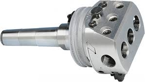
#2 Boring Head or Cutter Head
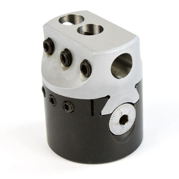
The boring head is using for mounting cutters while machining large diameter holes where a standard boring bar is unsuitable due to the smaller diameter or excessive overhang of the cutter. Boring heads have the maximum permissible diameter.
This device amply supports the tool and reduces machining time due to the larger number of cutting edges. The cutters may adjust by micrometre dials. it illustrates in the boring head.
#3 Facing head
The facing head is mounting on the end of the spindle. It comprises a flange provided with a diameter slide-way on which the tool carrying a bracket may be adjusted.
The bracket may be fed radially or located and clamped at the center to support a long boring bar. A facing head enables the enlarging of large diameter holes, facing an external turning operation. it is illustrated in the facing head.
Advantages of Horiztaonl Boring Machine
The following are the advantages of a horizontal boring machine:
- Some horizontal boring machines have the advantage of producing very large machined parts, which is something that other machining tools do not have.
- Depending on the machine, horizontal boring machines can make several cuts simultaneously and run at a high cutting speed.
- This is especially helpful in situations where businesses need to produce and deliver a lot of mechanical parts quickly.
- The horizontal boring machines are designed to guarantee that the drilling is always reliable and precise.
- Horizontal boring machines with computer controls minimize the possibility of human error and guarantee consistently precise cuts.
Download Pdf of this article

Conclusion
That’s it. Thanks for reading. I hope I have covered everything about the “Horizontal Boring Machine.” It would be helpful if you could let me know if there was anything I missed or if you have any doubts about anything I wrote.
Please share this article with your friends if you find it interesting.
Want free PDFs direct to your inbox? Then subscribe to our newsletter.
Read next:
Please send me details on mail
Subscribe to our newsletter to receive our blog post directly to your inbox.