In this post, you’ll learn What is Twist Drill and How it is used? With Its Parts, Types, and Nomenclature of Twist Drill. Also, you can download the PDF file at the end of this article.
Twist Drill Definition
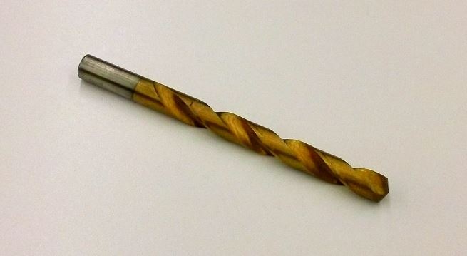
The most popular type of drill in use today is the twist drill. It was basically formed by twisting a flat piece of tool steel longitudinally for several revolutions, then grinding the diameter and point.
Currently, twist drills are manufactured by two machining spiral flutes or grooves that run lengthwise around the body of the drill.
A twist drill is an end cutting tool. Different types of twist drills are classified by Indian Standard Institute according to the type of shank, length of the flute, and overall length of the drill.
You might like: Milling Machine: Parts and Working Principle
Types of Twist Drill
Following are the types of twist drill:
- Short Series or Jobbers Parallel Shank Twist Drill
- Sub Series Parallel Shank Twist Drill
- Long Series Parallel Shank Twist Drill
- Taper Shank Twist Drill
- Taper shank Core Drill (Three or Four Fluted)
- Oil Tube Drill
- Centre Drills
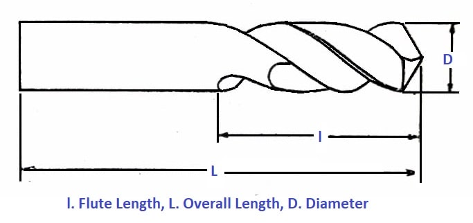
#1 Short Series or Jobbers Parallel Shank Twist Drill
The drill has two parallel shanks of approximately the same diameter as the cutting end. The diameter of the drill ranges from 0.2 to 16 mm increasing by 0.02 to 0.03 mm in the lower series to 0.25 mm in the higher series. The figure illustrates the drill.
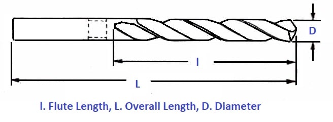
#2 Sub-Series Parallel Shank Twist Drill
The drill is a shortened type of parallel shank twist drill, the shortening being on the flute length. The diameter of the drill ranges from 0.5 to 40 mm increasing by 0.3 m in the lower series to 0.25 to 0.5 mm in the higher series. The figure illustrates the drill.
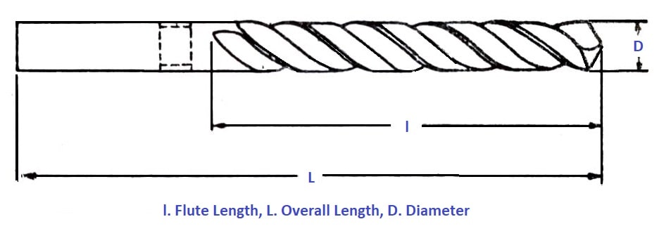
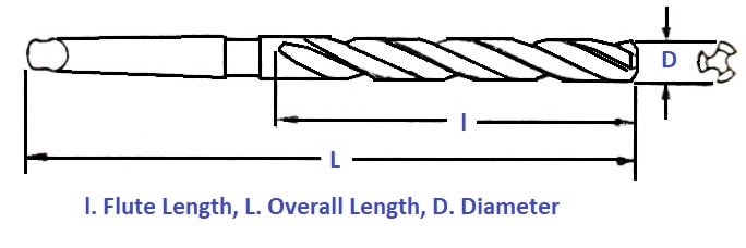
#3 Long Series Parallel Shank Twist Drill
The drill has two helical flutes with a parallel shank of approximately the shank diameter as the cutting end, which however does not exceed the diameter at the drill point.
The overall length of this drill is the same as that of a taper shank twist drill of the corresponding diameter. The diameter varies from 1.5 to 26 mm increasing by 0.3 mm in the lower series to 0.25 mm in the higher series. The figure illustrates the drill.
#4 Taper Shank Twist Drill
The drills have two helical flutes with a tapered shank for holding and driving the drill. The shank for these drills conforms to Morse tapers. The diameter ranges from 3 to 100 mm.
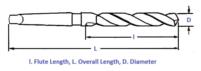
The diameter increases by 0.3 mm in the lowest series having Morse taper shank No. 1, by 0.25 mm in Morse taper shank numbers 2 and 3, by 0.5mm in Morse taper shank No. 4, and by 1 mm in Morse taper shank number 5 and 6.
The Morse taper shank is used below 6 mm size is not preferred. A drill gauge allows any drill to be easily selected by truing into the holes of the gauge. The figure illustrates the drill.
#5 Taper Shank Core Drill (Three or Four Fluted)
These types so drills are designed for enlarging cored, punched, or drilled holes. These drills cannot originate a hole in solid material because the cutting edges do not extend to the center of the drill. The metal is removed by a chamfered edge at the end of each flute.
Cored drills provide better-finished holes than those cut by normal two-fluted drills. The cutting action of a core drill is similar to that of a rose reamer and is used as a rough reamer. In some cases, a two-fluted twist drill is chosen to originate a hole half the required size, and the rest is finished by three or four-fluted drills. The figure illustrated the drill.
#6 Oil Tube Drill
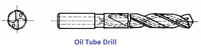
The oil tube drills are utilized for drilling deep holes. Oil tubes run lengthwise spirally through the body and carry the oil directly to the cutting edges.
Cutting fluid or compressed air is pushed through the holes to the cutting point of the drill to separate the chips, cool the cutting edge and lubricate the machined surface. The figure illustrates the oil tube drill.
#7 Centre Drills
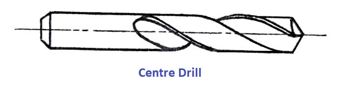
The center drills are straight shank, two fluted twist drills used when center holes are drilled on the ends of a shaft. They are made in finer sizes. The figure illustrates the drill.
Let’s now talk about the nomenclature of a twist drill.
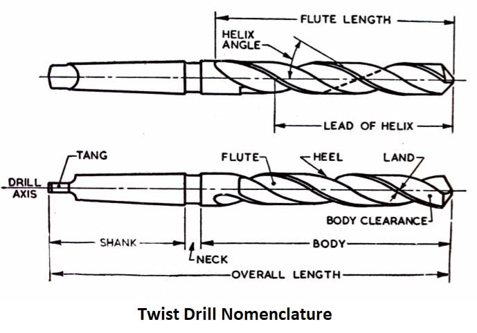
Twist Drill Nomenclature
The following are the twist drill nomenclature, definitions, and functions of the different parts of a drill illustrated in the figure.
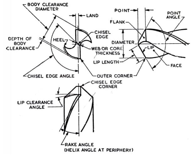
The following are the twist drill nomenclature:
- Axis
- Body
- Body clearance
- Chisel edge
- Chisel edge corner
- Face
- Flank
- Flutes
- Heel
- Lands
- Lip (cutting edge)
- Neck
- Outer corner
- Point right hand cutting drill
- Shank
- Tang
- Web
#1 Axis
The longitudinal center line of the drill.
#2 Body
That portion of the drill increases from its extreme point to the origin of the neck, if present, otherwise increasing to the origin of the shank.
#3 Body Clearance
That portion of the body surface is reduced in diameter to provide diameter clearance.
#4 Chisel Edge
The edge is formed by the intersection of the flanks. The chisel edge is also sometimes called the dead center. The dead center or the chisel edge acts as a flat drill and cuts its own hole in the workpiece.
A large amount of axial thrust is required to cut the hole from the chisel edge. In some drills, the chisel edge is made spiral instead of a straight one. This reduces the axial thrust and improves the hole location. The chances of production of oversize holes are also reduced.
#5 Chisel Edge Corner
The corner is produced by the intersection of a lip and the chisel edge.
#6 Face
The portion of the flute surface adjacent to the lip one which the chip impinges as it is cut from the work.
#7 Flank
The surface at a drill point extends behind the lip to the following flute.
#8 Flutes
The groove in the body of the drill gives lip. The uses of the flutes are:
- To From the cutting edges on the point.
- To allow the chips to escape.
- For to cause the chips to curl.
- To allow the cutting fluid to enter the cutting edges.
#9 Heel
The edge is produced by the intersection of the flute surface and the body clearance.
#10 Lands
The cylindrical ground surface at the major edges of the drill flute. The land width is measured at the right angle of the flute helix. The drill is full size only across the lands at the pointed end. Land keeps the drill aligned.
#11 Lip (cutting edge)
The edge is formed by the intersections of the flank and face. The requirements of the drill lips are:
- Both lips should be at the same angle of inclination with the drill axis, 59° for general work.
- The lips should be of equal length.
- Both lips must be given with the correct clearance.
#12 Neck
The diameter between the body and the legs of the drill is partially reduced. The diameter and other details of the drill are engraved on the neck.
#13 Outer Corner
The corner is formed by the intersection of the flank and face.
#14 Point
The sharpened end of the drill consists of all that part of the drill which is shaped to produce lips, faces, flanks, and a chisel edge.
#15 Right-Hand Cutting Drill
A drill that cuts when rotating in a counter-clockwise direction is viewed on the pointed end of the drill.
#16 Shank
That part of the drill by which it is held and driven. The most common types of shank are the taper and straight shank. The taper shank provides means of centering and holding the drill by friction in the tapered end of the spindle.
#17 Tang
The flattened end of the taper shank is designed to fit inside a drift slot in the spindle, socket, or drill holder. The tang ensures a positive drive of the drill from the drill spindle.
#18 Web
The central portion of the drill is situated between the roots of the flutes and extends from the point toward the shank; the pointed end to the web or core forms the chisel edge.
Materials of Twist Drill
Many twist drills are constructed of high-speed steel, either individually or in conjunction with a carbon steel shank that is attached to the body. Cobalt alloys are used in some Twist drills, while cement carbide inserts are used in others.
Advantages of Twist Drill
The advantages of a twist drill include the following:
- The efficiency of the twist drill tool is higher.
- Additionally, it saves time because the workpiece can be quickly drilled at a higher speed and feed.
- While other tools require high power to complete an operation, the twist drill requires less power.
- The flute makes it simple for the workpiece’s unwanted material cuts to be removed.
Disadvantages of Twist Drill
The disadvantages of a twist drill include the following:
- There is a chance of breaking if the tool has a smaller diameter.
- In comparison to other tools like Single Point Cutting Tool and Multi-Point, the finish is not as good.
- The tool may break due to heating if it is used continuously for an extended period of time. Therefore, coolant is necessary; it could be water or something else.
Application of Twist Drill
In the drilling machine, a twist drill is a tool that is used to carry out operations such as drilling holes into a workpiece. As a result of the diameter of the twist drill tool, the size of the hole in the workpiece depends on that.
Conclusion
So now, we hope that we have cleared all your doubts about Twist Drill Nomenclature. If you have still any doubts about “Twist Drill Nomenclature” you can contact us or ask in the comments.
That’s it thanks for reading. If you like our article then please share it with your friends. If you have any questions about any topic you can ask in the comment section.
Subscribe to our newsletter to get notifications of our new posts.
Download PDF of this article
You may be interested in these articles: