In this article, you will learn about different milling formulas used in milling operations with example. Download the PDF file at the bottom of this article.
Formulas for Milling Operation
Milling is the machining process that uses a rotary cutter to remove material by moving a cutter across the workpiece. This can be done on one axis or several axes, the speed and pressure of the cutter head are in a different directions.
We are going to look at some milling formulas for ease on the milling machine. Following are the important milling formulas that are very useful while performing any milling operation in a milling machine. Let’s see this one by one.
Milling Formulas
Following are the important terms used to determine the milling formula:
- Cutting speed
- Effective cutting speed
- Spindle speed
- Feed
- Maximum chip thickness
- Metal removal rate
- Specific cutting force
- Depth of cut
- Number of cutter teeth
- Machining time
Read Also: List of Important Terms Used in Lathe Machine Formula.
#1 Cutting Speed
The cutting speed of a milling cutter is its circumferential linear motion that results from rotation. It is expressed in meters per minute. The cutting speed can be obtained from the formula:
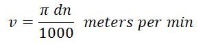
where,
- v = it is the speed of the cutter in m per min.
- d = cutter diameter in mm.
- n = Speed of the cutter in r.p.m.
#2 Effective Cutting Speed
It indicates the surface speed over the effective diameter (DCap). This is necessary in order to determine the correct cutting data at the actual depth of cut (ap).
It is used when you are working with round cutters, ball nose end mills, and cutters with large corner radii, as well as the cutter’s entry angle is less than 90 degrees.
#3 Spindle Speed
It is the number of revolutions per minute made by the milling tool on the spindle. This value is determined by the recommended cutting speed value for an operation.
#4 Feed
The feed in a milling machine is defined as the rate with which the workpiece advances under the cutter. The feed is expressed to the milling machine in the following three different ways:
1. Feed per tooth (Sz)
It is the distance that the work advances in the time between joining by two successive teeth is known as feed per tooth. It is usually represented in millimeters per tooth of the cutter.
2. Feed per revolution (Srev)
It is the distance that the work advances in the time the cutter turns through one complete revolution is known as feed per revolution. It is represented in millimeters per revolution of the cutter.
3. Feed per minute (Sm)
It is the distance by which the work moves in one minute is known as feed per minute. It is usually represented in millimeters per minute.
The feed per tooth, the feed per cutter revolution, and the feed per minute are related by the formula which is given below.
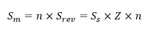
where,
- Z = number of teeth in the cutter.
- n = Speed of the cutter in r.p.m.
#5 Maximum Chip Thickness
This is the result of cutter engagement as it refers to (fz). Chip thickness is a required value when deciding whether to use the most productive table feed per tooth feed.
Average chip thickness: It is also a useful value in determining the specific cutting force used for net power calculations.
Checkout: What is Gear Cutting? Their Types [Advantages & Disadvantages]
#6 Metal Removal Rate
This is the volume of metal removed in cubic mm per minute (inch3/minute). It is designed using values for cutting depth, width, and feed.
#7 Specific Cutting Force
A material constant is a factor used for strength calculations and is expressed in N/mm2.
#8 Depth of Cut
It is defined as the thickness of the material removed in one pass of the work under the cutter. The depth of cut is the perpendicular length that is measured between the original and final surface of the workpiece and is represented in mm.
#9 Number of Cutter Teeth
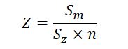
The number of teeth on a milling cutter should be properly designed for effective machining operation. Knowing the speed and feed to which the cutter will be subjected while in an operation, the number of cutter teeth can be derived from the feed formula. The number of cutter teeth is calculated from the equation:
The coarse teeth cutter having a lesser number of teeth on their periphery are efficient in metal machining. The following are the advantages of a coarse teeth cutter.
- Greater chip space may be provided.
- Cutter tooth cross-section may be increased thereby increasing its strength.
- A greater amount of rake angle can be provided on the cutter.
- Less power is required to drive the cutter.
- Less sliding friction is produced between the tooth and the work. This reduces the development of heat.
- Longer life of the cutter may be obtained as the number of regrinds can be increased.
#10 Machining Time
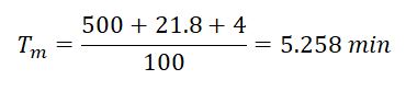
The machining length (lm) is divided by the table feed (vf). The time required for any operation to mill the surface can be calculated from the formula:
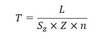
where,
- T = it is the time required to complete the cut in minutes.
- L = it is the length of the table travel to complete the cut in mm.
- Ss = it is the feed per tooth in mm.
- Z = it is the number of teeth in the cutter.
- n = it is the cutter r.p.m.
The figure shows the length of the table travel ‘L’ is composed of two parts: the length of the work “C” and the approach length “A”. The approach “A” is the distance through which the cutter must be moved before the full depth of cut is reached.
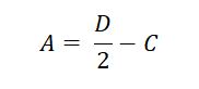
#1 Approach length for plain milling cutter:

Approach “A” for a plain milling cutter can be determined by the equation:
where,
- A = the approach in mm.
- B = the depth of cut in mm.
- C = the diameter of the cutter in mm.
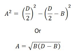
#2 Approach length for face milling cutter:

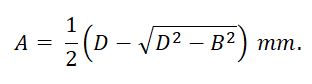
Referring to the above figure, the approach length for a face milling cutter can be calculated from the equation:
where,
- A = it is the length of approach in mm.
- D = it is the cutter diameter.
- B = it is the width of the work.
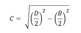
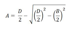
Substituting the value of “C” in equation “A”
Read Also: Formation of Chips In Metal Cutting [Explained]
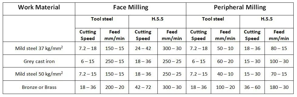
Average Cutting Speed and Feed of Different Materials
Let’s Consider One Example
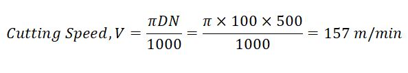
#1 Example
Evaluate the cutting parameters for the slab milling operation for the following date:
- Milling cutter diameter = 100 mm
- Cutter speed = 500 r.p.m
- Width of cutter = 100 mm
- Depth of cut = 5mm
- Table feed = 100 mm/min
- Length of workpiece = 50 cm
- Width of workpiece = 80 mm
- Number of teeth in cutter = 8
Ans: Cutter diameter = 100 mm, cutter speed = 500 r.pm.
MRR = b.d.F
b = width of job = 80 mm, d = depth of cut = 5 mm, F = Table feed = 100 mm/min.

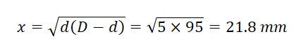
l = 500 mm, Here y = 4 mm
Conclusion
This is a complete list of milling formulas and definitions that are useful in any milling process and milling cutter. Understanding how to calculate accurate cutting speed, feed per tooth, or metal removal rate and machining time is very important for good results in any milling operation.
That’s it. If you still have any questions about “Milling Formulas” you can ask in the comments I’ll respond to you. If you like this article then share it with your friends.
Subscribe to our newsletter. It’s free!
Download PDF of this article:
Read more articles on machines:
- 8 Different Types of Drilling Machine [Explained with Pictures]
- What are the types of mechanisms used in shape machines? [PDF]
- 12 Different Types of CNC machines with PDF
External Links:
PDF file is not download… how to take it
Hi there. I have sent the PDF file to your inbox.