In this article, you will learn what is flow control valves? Its parts, working, and types of flow control valves are explained with pictures.
You can also download the PDF file at the bottom of this article.
What is Flow Control Valve?
The valves which are mainly used to regulate the flow of fluid in hydraulic circuits are known as “flow control valves”. The flow control valves are widely available in many different types according to their use.
In hydraulics, flow control valves are used to control the amount of oil supplied to various parts within a hydraulic system. In this way, the momentum of a cylinder or the rotational speed of a hydraulic motor can be controlled.
However, a basic flow control valve has an opening that can be changed to increase or decrease the flow rate. The many benefits of using flow control valves include the variety of materials from which they can be made (such as brass, carbon steel, stainless steel, and zinc).
Flow control valves can provide many choices for simple and complex systems that adjust for pressure, temperature, and other flow variables.
Read also: what are the different properties of fluid?
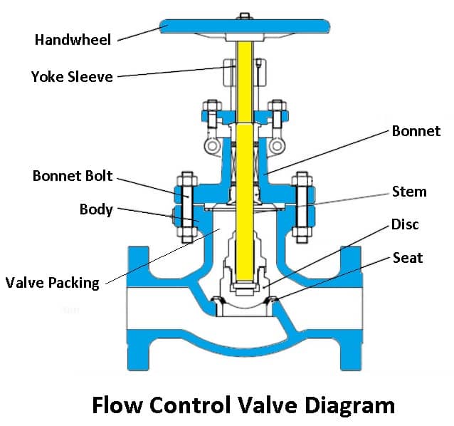
Parts of Flow Control Valve
Following are the parts of the flow control valve:
- Body
- Bonnet
- Trim
- Disk and seat
- Stem
- Actuator
- Handwheel
- Valve packing
Read Also: What is Fluid Coupling or Fluid Drive?
#1 Body
It is the main part of the flow control valve, in which all other parts are kept together by a structure called the body. The piping in the valve body is achieved with the help of bolts and welded joints. It is usually made of cast iron and is also called a valve shell.
#2 Bonnet
The bonnet is a cover that is used for the opening in the body and is divided into two parts which are fastened together. Some valve bonnets are used only as covers while some of them are used for valve interior accessories.
#3 Trim
The trim is usually presented on the inside of the valve and consists of the stem, sleeve, seat, and disc. Valve performance can be detected by the seat and disc interface.
#4 Disk and Seat
A disc is an essential part of the flow control valve that allows and restricts fluid flow. If the disc is in the closed state then the total system pressure is applied to the disc and the pressure is exerted towards the outlet.
#5 Stem
These are liable for the connection of the actuator and the disc, which holds the disc in position. The connection is done by the threads and welded joints. Generally, two types of the stem are used which are non-rising stem and rising stem.
#6 Actuator
This is the main part of the flow control valve, which is driven by the stem and disc assembly. Control valve actuators may be operated manually or by an electric motor.
#7 Handwheel
It is a common type of valve actuator. A valve handwheel is used to manually control the opening and closing of the valve.
#8 Valve Packing
It is a sealing system, that has a deformable material in the solid form or split rings held in a packing box. These are used for packing in valves which consequently prevents leakage between stem and bonnet.
Working of Flow Control Valve
The flow of the fluid can be controlled by changing the place through which it is passing. In this, a pressure drop occurs and this must be considered when choosing a flow control valve.
In a hydraulic circuit, the pressure fluctuates across the load, sometimes more or less. Although the inlet pressure is constant, the pump is delivering fluid at constant pressure but the outlet pressure can vary.
To avoid this fluctuation in load we can easily install a pressure compensated flow control valve. By using this flow control valve, the flow rate can be kept constant even under variable loads.
These valves have a spool and by changing the position of the spool, the field direction of the passage can be adjusted. Therefore, the required flow can be maintained during the flow of the fluid through the control valve.
Types of Flow Control Valves
Following are the types of flow control valves:
- Gate valve
- Plug valve
- Needle valve
- Non-return valve
- Butterfly valve
- Pressure compensated flow control valves
- Pinch valve
- Globe valve
- Diagram valve
- Ball valve
Read Also: What are the applications of Bernoulli’s Equation?
#1 Gate Valve
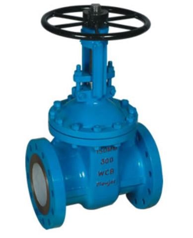
The valve controls the flow of the oil in a pipe by moving a flat plate called a gate or disc valve. Gate is built perpendicular to the length of the pipe with the help of a handwheel.
This mechanism is achieved by connecting the gate with the handwheel through a threaded spindle that rotates in the valve body. The advantage of a gate valve is that it offers little or no resistance to flow when it is fully open. It is usually made up of gunmetal.
#2 Plug Valve
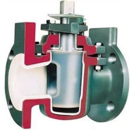
As the name suggests, this valve is having a plug. This plug can be turned to move its ports to control the flow of oil and it features to reduce the friction between the plug face and the body seat when the turning of the plug.
The valve consists of a tapered wedge mechanically seated in the body. The tapered edge has a rectangular window. When the valve is fully open rectangular window aligns itself with the holes running through the valve body.
#3 Needle Valve
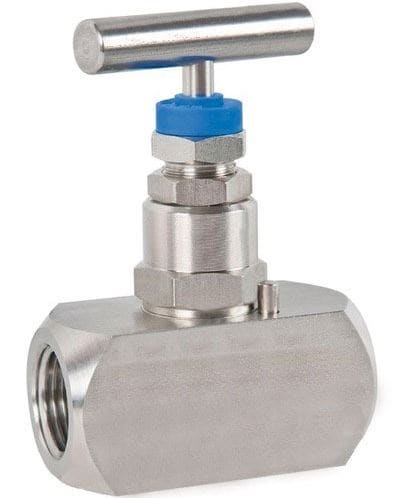
It is a kind of screw-down stop valve. Its use is restricted to small sizes which have the body ends in line or right angles with each other or maybe oblique type.
Here disc is in the form of needlepoint. By rotating the handwheel, the tapered needle advances, and the area of the valve seat decreases. Hence the oil flow is gradually reduced. These valves are used in hydraulic systems in lines of delicate pressure gauges.
#4 Non-return Valve
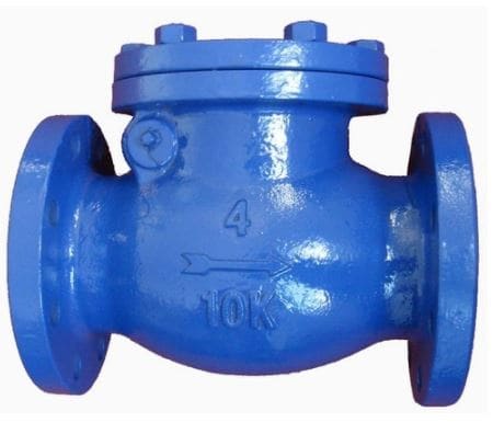
The non-return valve permits flow in one direction and stops the flow completely in one direction. It consists of a valve body, a poppet, a spring, and a seat.
When the force of fluid is available at the inlet port exceeds the strength of the spring and the backpressure of oil the poppet is pushed up and the valve opens to permit the flow through it. When the oil is flow is reversed, the valve piston is pushed back to its seat, completely blocking the flow.
#5 Butterfly Valve
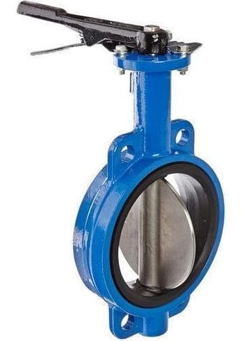
The butterfly valve has a circular disc that can be rotated through one complete revolution. The circular disc has a diameter equal to that of a pipe.
The valve is connected across both faces by two pipes with flanges. A circular disc is made to rotate around an axis passing through the vertical diameter of the disc. This type of flow control valve is used for controlling moderate flow.
Read Also: What are the uses of Pneumatic System? [Explained with Examples]
#6 Pressure Compensated Flow Valve
The pressure compensation flow valve provides a uniform volume flow rate independent of the pressure drop across the valve. On the other hand, the non-pressure-compensated valves have a variable flow rate that changes as the pressure in the valve fluctuates.
#7 Pinch Valve
These are types of flow control valves, which are inexpensive and are used in almost all industries. It consists of flexible elements such as rubber tubes for sealing purposes. They are designed to give a tight seal around trapped solids with their flexibility, these rubber tubes are the moistened part in a pinch valve.
Pinch valves are perfect for liquids that contain large amounts of suspended solids. The valve body acts as a built-in actuator, reducing the need for expensive operators such as pneumatic, hydraulic, or electric operators.
#8 Globe Valve
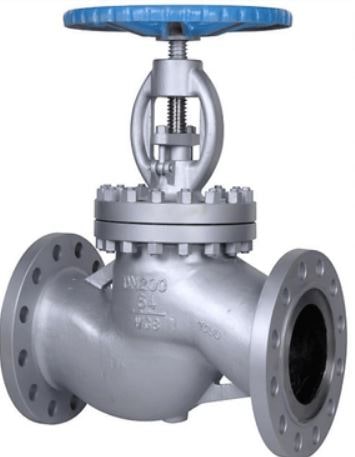
These are considered valuable for starting, stopping, and regulating the flow in a linear motion. Globe valves are used for throttling applications because the disc of the valve can be completely removed from the flowline and are also capable of closing the flowline completely.
Unlike the other types that are straight-through valves, these valves produce slightly high-pressure drops. The closure in a globe valve is opened by means of a plug that covers a flat bottom and is then lowered onto a horizontal seat in the center of this valve. The plug in the globe valve lifts when the user opens it, and this allows the fluid to flow.
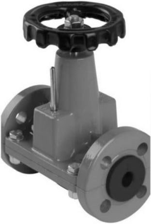
#9 Diaphragm Valve
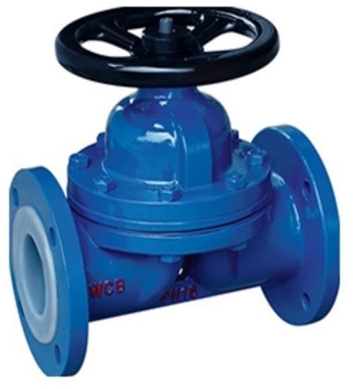
These valves are built to handle conditions that require erosive, corrosive, and dirty services. It consists of a flexible disc that reaches the top of the valve body along with the seat to form a seal. These are used to control the opening or closing of the valve.
These valves work by an elastomeric diaphragm in the valve body, rather than an elastomeric liner, which is attached to a compressor to isolate the closure element from the fluid flow. This gives the advantage that they feature a leak-proof seal and are easy to maintain.
#10 Ball Valve
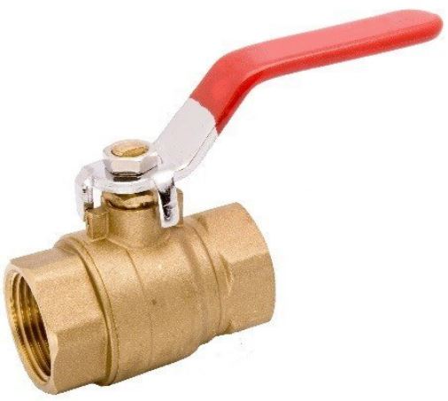
Ball valves are commonly used in a variety of industries because of their low cost, durability, and excellent closing capability. These are similar to a butterfly valve, they are not suitable for flow control applications as they require high accuracy and control.
This is because a high level of torque is required to open and close a ball valve which prevents an operator from making fine adjustments. The ball valve is used for filling a tank with reasonable accuracy. A trunnion or V-port ball valve design is usually the best type.
Conclusion
As I discussed above, flow control valves are used for plumbing, mechanical, and gas distribution applications. Therefore, there are many factors to consider when selecting a suitable flow control valve such as media type, valve function, application conditions, actuation method, and maintenance requirements.
So now, I hope I have cleared all your doubts regarding this topic. But, if you still have any doubt about “Flow Control Valve“, you can contact us or ask freely in the comments. If you liked our article, then please share it with your friends.
Want free PDFs of our upcoming posts, just subscribe to our newsletter.
Download PDF of this article:
You might like to read more in our blog:
- How Pascal’s Law explained? Its Formula, Derivation, Applications
- What is Reaction Turbine? Their Parts, Types and Working Principle
- Reciprocating Pumps: Definition, Types, Parts, Working and Applications
Furthermore, check out these External Links:
Thank you so much for sharing this reference. Very useful information for my job
You’re welcome.
hi this is so good
please how can i download the PDF of this book.
Don’t worry, I sent you the PDF file of this article to your inbox.