In this article, you will learn the different parts of transformer and their functions. All are explained with Names & Pictures.
You can also download the PDF file of this article at the end.
What is Transformer?
An electrical component known as a transformer is used to move electrical energy between one electrical circuit to another or between several circuits. A changing magnetic flux in the transformer’s core results from a changing current in any of its coils.
As a result, any other coils wound around the same core experience a fluctuating electromotive force (EMF). AC voltage levels can be changed using transformers, classified as step-up or step-down types depending on whether they increase or decrease voltage level.
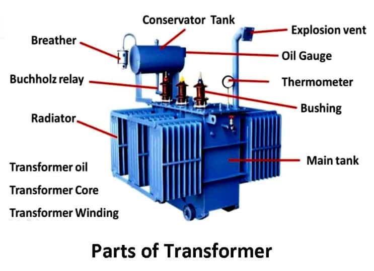
A transformer is composed of several unique components, each of which contributes to the overall performance of the transformer in a different way. The main components are the core, windings, insulating materials, transformer oil, tap changer, conservator, breather, cooling tubes, Buchholz Relay, and explosion vent.
Nearly all transformers have a core, windings, insulating materials, and transformer oil; transformers with more than 50 KVA have other components. Let’s discuss the working principle of these transformer parts.
Read Also: Different Types of Transformers and Their Working [Explained]
Parts of Transformer
Following are the main parts of transformer:
- Core
- Winding
- Tank
- Insulation
- Transformer oil
- Terminals and bushings
- Breather
- Tap changer
- Radiators and fans
- Cooling tubes
- Buchholz relay
- Explosion vent
- Oil conservator
- Temperature gauge
#1 Core
Transformers are constructed using a core, which is the center of the transformer. These are used to support the windings. The primary and secondary windings are supported by the core, which offers an electromagnetic flux path with low reluctance.
It is constructed from thin sheets of premium grain-oriented steel separated by thin insulating materials. The carbon content of the core steel is kept below 0.1% to reduce hysteresis and eddy currents.
Improved core construction methods and highly permeable material help create a desirable, low reluctance flux path and confine flux lines to the core. Core type and shell type are the two different types of core constructions.
#2 Winding
The windings, divided into several coils, enable voltage lowering between adjacent layers. Several turns of copper or aluminum conductors produce this winding and are insulated from the transformer core and one another.
Transformer winding types and configurations are determined by factors like current rating, short circuit power, temperature rise, impedance, and surge voltages. Primary and secondary windings are based on supply, which means they apply input and output voltages, respectively.
The primary and secondary winding is divided into two sections, the high voltage (HV) winding, and the low voltage (LV) winding. In contrast, high-voltage and low-voltage windings can be distinguished based on the voltage range. The number of turns and its current carrying capacity determine the winding to use.
Read Also: Different Types of Capacitors and Their Applications [PDF]
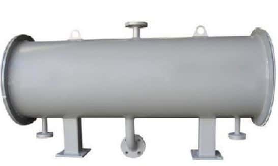
#3 Tank
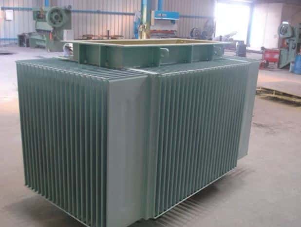
Transformer tanks are used to hold, protect, and cool the windings and core in an electrical distribution transformer. It serves as a container for oil and support for all other transformer accessories and protects the core and windings from the outside environment.
Tank bodies are created by shaping rolled steel plates into containers and adding lifting hooks and cooling tubes. Aluminum sheets are also employed rather than steel plates to lighten the product and prevent stray losses.
#4 Insulation

Most power transformers have cellulose (paper/pressboard) and oil as insulation materials. Copper is used to make these windings due to their high conductivity and ductility. These components shield the transformer core and the primary and secondary windings from one another.
Insulation is required between the core and the windings, as well as between each winding turn and the tank for all current-carrying components. The insulators must withstand high temperatures, have good mechanical qualities, and have high dielectric strength.
Transformers can sustain the most severe damage if the insulation fails. Transformer insulation is generally made of synthetic materials, paper, cotton, and other materials. The most fundamental components of a transformer are its core, winding, and insulation.
Read Also: Understand The Different Types of Electric Motors [Complete Guide]
#5 Transformer Oil
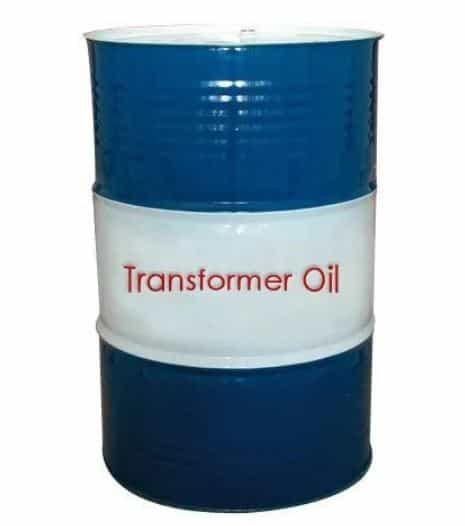
The core and coil assembly are insulated and cooled using the transformer oil. The transformer’s core and windings must be completely submerged in the oil, which typically contains mineral oils with hydrocarbons.
Transformer oil provides additional insulation between conductor parts, improves heat dissipation, and detects faults, especially in oil-immersed transformers. Transformer oil has a 310°C flashpoint, a 2.7°C relative permeability, and a density of 0.96 kg/cm3.
#6 Terminals and Bushings
Transformers have terminals that are used for connecting incoming cables and cables leaving the transformer. Normally, they are mounted on the bushings and are connected to the ends of the windings by means of cables.
An insulator bushing is a type of device that forms a barrier between the terminals of the power source and the tank that contains it. They are positioned above the transformer tanks. For the conductors connecting terminals to windings, they provide a secure path. Porcelain or epoxy resins are used to create these devices.
Read Also: Types of Insulators Used In Power Transmission Lines [PDF]
#7 Breather
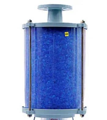
A breather is an add-on for liquid-immersed power transformers that are connected to the transformer tank. It is a crucial device for preventing moisture from getting into the oil. The breather is a cylinder filled with silica gel that is used to keep the air entering the tank dry.
This is because moisture can cause internal faults in the insulation when it reacts with the insulating oil, which is why it is essential to maintain dry air. This is why there shouldn’t be any moisture in the air, and the breather accomplishes this.
#8 Tap Changer
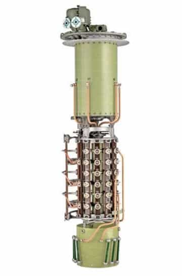
A tap changer’s job is to control a transformer’s output voltage. This is accomplished by changing the number of turns in one winding, which affects the transformer’s turn ratio. A de-energized tap changer and an on-load tap changer are the two different types of transformer tap changers (DETC).
On-load tap changers can operate while the current is still flowing to the load, whereas off-load tap changers can only operate when the transformer is not supplying any loads. These days, automatic tap changers are also accessible.
Read Also: Understand The Working & Application of DC Generator
#9 Radiators and Fans
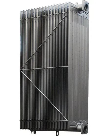
The transformer is made up of exterior radiator tubes, which are cooled by air from fans installed on the tank’s walls. Most of the time, heat is produced as a result of the power that is lost in the transformer. Most dry transformers use natural air cooling.
However, various cooling techniques are used when it comes to oil-immersed transformers. Radiators and cooling fans are mounted on the transformer tank based on the kVA rating, power losses, and level of cooling requirements.
The surrounding transformer oil absorbs the heat produced in the core and winding. At the radiator, this heat is released. Using cooling fans attached to the radiators, forced cooling is accomplished in bigger transformers.
#10 Cooling Tubes
In order to cool the transformer oil, cooling tubes are used, as their name suggests. It’s possible for oil to circulate naturally or artificially inside the transformer.
When the oil temperature rises, the hot oil naturally rises to the top during natural circulation. In contrast, the cold oil naturally lowers, whereas an eternal pump is used to move the oil between the hot and cold zones in forced circulation.
Read Also: Different Types of Inductors and Their Applications [PDF]
#11 Buchholz Relay
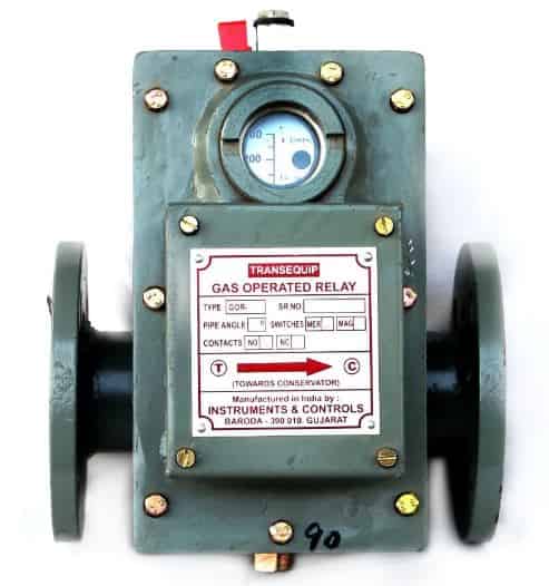
Buchholz relays are critical components of oil-immersed transformers rated above 500kVA. Usually what happens, transformer oil short circuits produce enough heat to cause the oil to break down into gases like methane, carbon monoxide, and hydrogen.
Buchholz relays are mounted on the pipe connecting the conservator tank to the main tank. They sense these gases and activate the trip and alarm circuits. The trip circuit interrupts the current flow and activates the circuit breaker controlling the primary winding.
#12 Explosion Vent
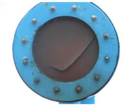
An explosion vent, which is a component of the transformer, serves as a means for oil and air gases to escape during an emergency. It typically consists of a metallic pipe that is held just above the conservator tank and has a diaphragm at one end.
When there is an oil leak, the pressure inside the tank can reach dangerous peaks. When this happens, the diaphragm ruptures at a relatively low pressure, releasing the forces inside the transformer into the atmosphere.
#13 Oil Conservator
The oil conservator tank’s purpose is to offer enough space for transformer oil to expand and contract. It varies in accordance with the fluctuation in the main tank’s ambient temperature for transformer oil.
This cylindrical drum-shaped structure is mounted on top of the transformer’s main tank. It has a Buchholz relay mounted on the pipe connecting it to the main tank. To show how much oil is in the conservator tank, a level indicator is also present on the oil conservator.
#14 Temperature Gauge
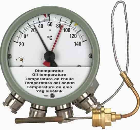
An instrument used to monitor the temperature of a power transformer is called a temperature gauge. It is placed on top of the tank to measure the temperature of the transformer. There is an alarm or light on this meter which alerts you when the temperature rises.
Closing It Up
So now, I expect I’ve covered everything about “Parts of Transformer. “ If you still have any doubts or questions on this topic, you can contact us or ask in the comments. If you like this article, then please share it with your friends.
Want free PDFs direct to your inbox? Then subscribe to our newsletter.
Download PDF of this article:
You might like to read more in our blog:
Great breakdown of transformer components! The detailed explanations really helped clarify their functions for me. I appreciate the inclusion of the PDF as well—it’s a handy resource for future reference. Thanks for sharing this informative post!
Glad you found it helpful!
Very concise and informative article. Easy for a beginner to
Thank you! I’m glad you found it concise and informative.
Very helpful post and a good site to browse.
Thanks for your feedback.
Good site
Thank you.