In this article, you’ll learn what is fluid coupling? Its diagram, parts, working, and advantages are explained with pictures.
Don’t forget to download the PDF file of this article at the end of it.
What is a Fluid Coupling?
Fluid coupling is a hydrodynamic device that uses transmission fluid to transfer rotational motion from one shaft to another. It is used in many industrial applications, marine propulsion systems, and automotive transmission systems.
It is a transmission driveline combination that replaces the flywheel with a hydraulic coupling and works on the same function as a modern torque converter, only without torque multiplication.
The fluid drive is one name for liquid coupling to transmit turning an effort from the engine to the clutch. It is located between the crankshaft and the clutch. Because the liquid coupling is a major part of the engine flywheel assembly, it is sometimes called a fluid flywheel.
Read also: What Is Overdrive Transmission And How It Works?
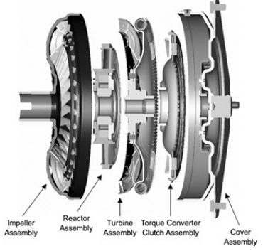
Parts of Fluid Coupling
Following are the parts of fluid coupling:
- Housing
- Impeller or pump
- Turbine
#1 Housing
Also known as a shell, it has an oil-tight seal, which helps to protect the drive shaft of the coupling. In addition, it also shields the impeller and turbine from external damage.
#2 Impeller or Pump
Since it acts as a centrifugal pump, it is also known as a pump. It is connected to the input shaft and referred to as an impeller.
#3 Turbine
The turbine is connected to the output shaft to which the rotational power is to be transmitted.
Read Also: Different Types of Transmission Systems
Working Principle of Fluid Coupling
The working principle of a liquid coupling is shown in the figure with the help of two fans. When one fan is turned on and faces toward the other the air stream makes the second fan turn, even though it is not switched on.
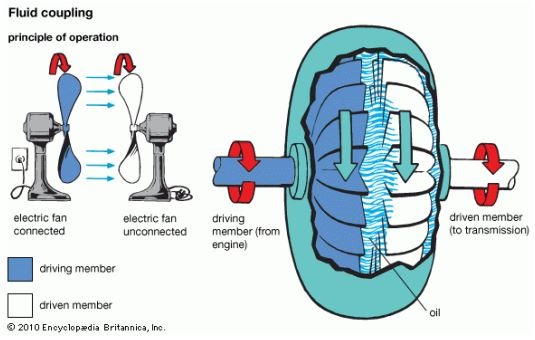
The first fan is the driving member and the second fan is the driven member or the runner. Air is the fluid used as the medium of power transmission. This is simple fluid coupling, with air serving as the fluid.
Read Also: What is Coupling? Different Types of Coupling
Working of Fluid Coupling
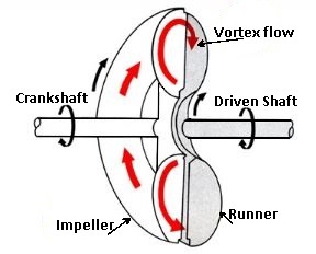
The Figure shows the diagram of a liquid coupling. It consists of, in general, two half-dough nut-shaped shells provided with interior fins that radiate from the hubs. One shell is attached to the crankshaft and is known as a driving member or an impeller. Another shell is fixed on the driven shaft and is known as a driven member or a runner.
The 2 shells are very close with their ends facing each other and attached in the housing so that they can rotate without rubbing each other. It is a complete assembly of a liquid coupling. The liquid (oil) is filled in the housing.
When the crankshaft turns, the oil trapped in the impeller fins impinges on the runner fins and causes it to move. In this way, the liquid transmits engine force to the clutch plate without any metal-to-metal contact.
The lag of the runner behind the impeller is called a slip. It depends upon the engine speed and load. The slip is maximum when the vehicle is at rest and the throttle is open, to cause the impeller to start circulating the oil.
The oil under these conditions moves in two general directions at the same time. It rotates at right angles to the shaft (rotary flow) and also circulates between the impeller and runner (vortex flow).
Read also: What Is Hydramatic Transmission?
Vortex Flow
The Vortex flow is at right angles to the rotary flow and is produced by oil trapped in the fins of the impeller. The oil flies out against the rounded interior because of the centrifugal force. The rotary flow starts the movement of the runner when it attains sufficient force and volume.
The vortex flow is high when the slip is 100% and decreases as the runner’s speed approaches that of the impeller. As a result, the efficiency of the liquid coupling increases rapidly from 0 at rest to nearly 99% at higher speeds.
In a typical liquid coupling, the runner would reach the same speed as the impeller, so as to receive all the power given to the coupling by the engine. In commercial design, the runner speed becomes nearly equal to that of the impeller only at the best operating condition, when the efficiency of the coupling is highest.
The liquid coupling is not suited for use with an ordinary gearbox. It is generally used in conjunction with epicyclic gears to provide a semi or fully-automatic gearbox.
The liquid coupling is always a major part of the engine flywheel assembly and hence it is also known as a fluid flywheel.
Read also: Difference Between Petrol and Diesel Engines [Explained]
Fluid Flywheel
Another design of the fluid flywheel is shown in the Figure. It consists of a slip housing which is rotated by the engine crankshaft. Inside the housing is a driven rotor which is connected by a shaft to the gearbox. The flywheel housing is divided into many cells using radial vanes.
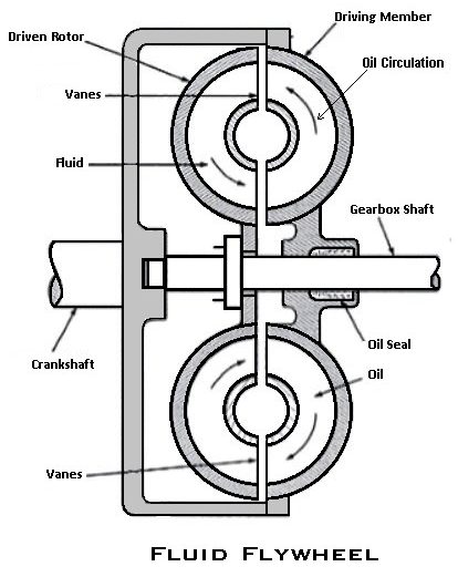
These cells correspond to similar openings in the driven rotor. As the driving member rotates, the fluid flows outwards due to the centrifugal force and circulates from the flywheel to the driven rotor.
Because the fluid is also carried cut round by the driving member, the fluid tends to rotate the driven rotor. Because the fluid is also carried out around by the driving member, the fluid tends to rotate the driven rotor. Thus the torque is transmitted to the crankshaft to the gearbox shaft.
The liquid flywheel requires less attention than friction clutches. Also, it needs no adjustment. The drive is taken up smoothly, the torsional vibration of the crankshaft and the transmission shocks when braking and going down a hill, and the clutch pedal is eliminated.
Read Also: What is the function of a Timing Belt in a Car?
Advantages of a Fluid Coupling
- A liquid coupling, when used with a conventional clutch and transmission enables the driver to use the clutch and gears with less skill and fatigue than with an all-mechanical linkage.
- If the driver fails to de-clutch or shift to neutral before coming to a stop, the coupling will slip sufficiently to prevent stalling the engine.
- Unskilled clutch engagement or selection of improper gear will not produce chattering and bucking.
- Any sudden load is cushioned and absorbed by the coupling so that the dynamic stresses on the gear teeth of the transmission and rear axle are greatly reduced.
- The vehicle may be started in high gear when equipped with a liquid coupling because the coupling shills sufficiently to enable the engine to speed up.
- Liquid coupling at low speeds is not as efficient as mechanical ones. It reduces engine braking when slowing down and requires high speed to start the vehicle.
Disadvantages of Fluid Coupling
- Fluid couplings use more energy because they are less efficient than mechanical gear systems.
- They are unsuitable for applications that demand a wider speed range.
- For particular uses, the higher cost of fluid coupling compared to a mechanical gear system may be unaffordable.
- Because the fluid may need to be changed or get polluted, the fluid coupling needs to be maintained.
Application of Fluid Coupling
- In the auto industry, it transfers energy from the motor to the wheels instead of the clutch.
- Fluid coupling is a propellant component utilized in systems for maritime propulsion.
- In many different industries, it is used to transport energy for devices including mixers, ball mills, conveyors, crushers, fans, and pumps.
That’s It. Thanks for reading. If you have any questions on the “fluid coupling or fluid drive” leave a comment I’ll respond. If you find this article helpful please share it with your friends.
Want free PDFs direct to your inbox? Then subscribe to our newsletter.
Download PDF of this article:
Read Next:
- What is Manual Transmission? Parts, Working & Types
- How does a Wankel Rotary Engine works?
- Different Types of Turbochargers: Their Pros & Cons [PDF]
FAQs
Fluid couplings are hydrodynamic devices that convey spinning mechanical power. It has been utilized in place of a mechanical clutch in car transmissions.
It was found by Hermann Fottinger, MD. In 1950, he received patents for his inventions of the torque converter and fluid coupling.
The main benefit of fluid coupling is that it allows the operator to vary the speed of the power transfer without causing shock loading. For power transmissions, couplings can offer overload protection.
Fluid couplings are two-element drives that cannot multiply torque, while torque converters have a stator that alters the characteristics of the drive in high slippage periods, causing an increase in torque.
thank you for goods notes
You’re welcome.
Thanks a lot for sharing this with all of us you really recognise what you’re speaking about!
Bookmarked.
Thank you very much