In this article, you learn what is a clutch. Different types of clutches with parts, working principles, advantages, and more.
Download the PDF of this article at the end.
Clutch and Types of Clutches
In the clutch, one shaft is usually connected to an engine or another power unit (driving member), while the other shaft (driven member) provides output power for the work.
The clutches used in a motor vehicle are almost very similar in construction and operation. There are some differences in the details of the linkage as well as in the pressure plate assemblies.
In addition, some clutches for heavy-duty applications have a two-friction plate and an intermediate pressure plate. Some clutches are operated by hydraulic means. The dry single-plate type of friction clutch is almost used in American passenger cars.
The various types of clutches used in the automobile depend upon the type and use of friction.
Most designs of the clutches use many coil springs but some use a diaphragm or conical type spring. The type of friction materials also varies in the clutches of different passenger cars.
Read Also: Different Types of Car Sensors and Their Functions
Types of Clutches
Following are the different types of clutches:
Single Plate Clutch
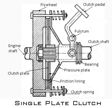
Single plate clutches are one of the most commonly used types of clutches used in most modern light vehicles. The clutch helps to transmit torque from the engine to the transmission input shaft. As the name states it has only one clutch plate.
It consists of a clutch plate, friction plate, pressure plate, flywheel, bearings, clutch spring, and nut-bolts arrangement.
The single-plate clutch has only one plate which is attached to the splines of the clutch plate. Single plate clutch is one of the main components of the clutch. The clutch plate is simply a thin metallic disc that has both side friction surfaces.
The flywheel is attached to the engine crankshaft and rotates with it. A pressure plate is bolted to the flywheel through the clutch spring, which provides the axial force to keep the clutch engaged position and is free to slide on the clutch shaft when the clutch pedal is operated.
A friction plate is fixed between the flywheel and the pressure plate. The friction lining is provided on both sides of the clutch plate.
Working
In a vehicle, we operate the clutch by pressing the clutch to peddle for disengagement of gears. Then springs get compressed and the pressure plate moves backwards. Now the clutch plate becomes free between the pressure plate and flywheel. Due to this now the clutch is getting disengaged and able to shift the gear.
This makes the flywheel rotate as long as the engine is running and the clutch shaft speed reduces slowly and then it stops rotating. As long as the clutch peddle is pressed, the clutch is said to be disengaged, otherwise, it remains engaged due to the spring forces.
After releasing the clutch pedal the pressure plate comes back to its original position and the clutch is again engaged.
Multiplate Clutch
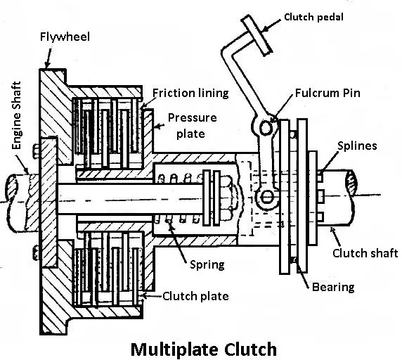
The multi-plate clutch is shown in the figure. These types of clutches use multiple clutches to make frictional contact with the flywheel of the engine. This transmits power between the engine shaft and the transmission shaft of a vehicle. The number of clutches means more friction surface.
The increased number of friction surfaces also increases the capacity of the clutch to transmit torque. The clutch plates are fitted to the engine shaft and gearbox shaft.
They are pressed by coil springs and assembled in a drum. Each of the alternate plates slides in grooves on the flywheel and the other slides in splines on the pressure plate. Hence, each different plate has an inner and outer spline.
The working principle of multiple clutches is the same as the working of the single-plate clutch. The clutch is operated by pressing the clutch pedal. The multiple clutches are used in heavy commercial vehicles, racing cars, and motorcycles for transmitting high torque.
The multiple clutches have two characters dry and wet. If the clutch is operated in an oil bath, it is known as a wet clutch. If the clutch is operated dry without oil, it is known as a dry clutch. The wet clutches are commonly used in connection with, or as a part of the automatic transmission.
Cone Clutch
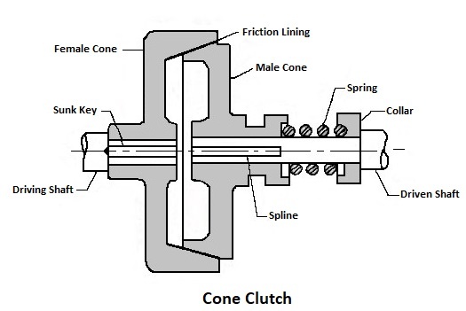
The figure shows the diagram of a cone clutch. It consists of friction surfaces in the form of cones. This clutch uses two conical surfaces to transmit torque by friction. The engine shaft consists of a female cone and a male cone. The male cone is mounted on the splined clutch shaft to slide on it. It has a friction surface on the conical portion.
Due to the force of spring when the clutch is engaged the friction surfaces of the male cone are in contact with the female cone. When the clutch pedal is pressed, the male cone slides towards the spring force, and the clutch is disengaged.
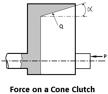
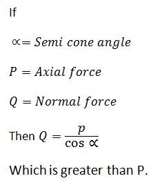
The main advantage of using a cone clutch is that the normal force acting on the friction surface is greater than the axial force, as compared to the single-plate clutch. That’s why the normal force acting on the friction surface is equal to the axial force.
The cone clutches are becoming old because of some disadvantages.
- Let’s consider the angle of the cone is smaller than 20°, the male cone tends to bind in the female cone and it becomes difficult to disengage the clutch.
- A small amount of wear on the cone surfaces has a considerable amount of axial movement of male cones, for which it will be difficult to allow it.
Centrifugal Clutch
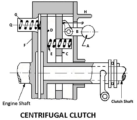
The below figure shows a centrifugal clutch. To keep the clutches in the engaged position centrifugal clutch uses centrifugal force, instead of spring force. In these types of clutches, the clutch is operated automatically depending on the engine speed. That’s why no clutch pedal is required to operate the clutch.
This made so easy for the driver to stop the vehicle in any gear without stalling the engine. Similarly, you can start the vehicle in any gear by pressing the accelerator pedal.
Working of Centrifugal Clutch
- It consists of weights A pivoted at B.
- When the engine speed increases the weights fly off due to the centrifugal force, operating the bell crank levels, which press plate C.
- The movement of plate C presses the spring E, Which ultimately presses the clutch plate D on the flywheel against the spring G.
- This makes the clutch engaged.
- The spring G keeps the clutch disengaged at low speeds at about 500rpm.
- The stop H limits the movement of the weights due to the centrifugal.
Semi-Centrifugal Clutch
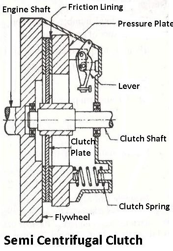
The semi-centrifugal clutch uses centrifugal force as well as spring force to keep it in the engaged position. The figure shows a semi-centrifugal clutch. It consists of levers, clutch springs, pressure plate, friction lining, flywheel, and clutch plate.
Construction of semi-centrifugal clutch:
A semi-centrifugal clutch has levers and clutch springs which are arranged equally on the pressure plate. The springs of the clutch are designed to transmit the torque at normal engine speed. While the centrifugal force helps in torque transmission at higher engine speeds.
At normal engine speeds, when the power transmission is low, the springs keep the clutch engaged, and the weighted levers do not have any pressure on the pressure plate.
At high engine speed when the power transmission is high, the weights fly off and the levers also exert pressure on the plate, keeping the clutch firmly engaged.
These types of clutches consist of less stiff springs, so that the driver may not get any strain while operating the clutch. When vehicle speed decreases the weights fall and the lever does not apply any pressure on the pressure plate.
Only the spring pressure is applied to the pressure plate which is enough to keep the clutch engaged. An adjusting screw is fitted at the end of the lever, using which the centrifugal force on the pressure plate can be adjusted.
Diaphragm Clutch
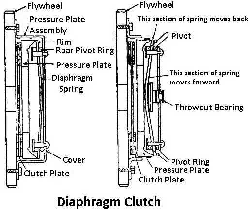
The diaphragm clutch consists of a diaphragm on a conical spring which produces pressure on the pressure plate for engaging the clutch. The spring may be finger or crown type attached to the pressure plate.
A tapered finger-type spring is shown in the figure. In these types of clutches, the engine power is transmitted from the crankshaft to the flywheel. The flywheel has friction lining and it is connected to the clutch as shown in the figure. The pressure plate is provided behind the clutch plate because the pressure plate applies the pressure on the clutch plate.
In the diaphragm clutch, the diaphragm is a conical shape of the spring. When we press the clutch pedal the outside bearing moves towards the flywheel pressing the diaphragm spring which pushes the pressure plate backward.
By doing this the pressure on the plate is removed and the clutch will get disengaged. When we release the clutch pressure peddle the pressure plate and diaphragm spring will come back to its normal position and the clutch will get engaged.
Advantages:
- These types of clutches have no release levers because the spring acts as a series of levers.
- The driver does not need to apply such heavy pedal pressure to hold the clutch disengaged as with the coil spring type in which the spring pressure increases more when the pedal is depressed to disengage the clutch.
Dog and Spline Clutch
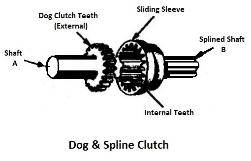
A dog is a type of clutch that is used to lock two shafts together or to connect a gear and a shaft. The two parts of the clutch are a dog clutch which has external teeth and another one is a sliding sleeve which has internal teeth.
Both shafts are designed in such a way that one will rotate another one at the same speed and will never slip. When the two shafts are connected then you can say the clutch is engaged. To disengage the clutch, the sliding sleeve moves back on the splined shaft to have no contact with the driving shaft.
The dog and splined clutch are mostly used in manual transmission vehicles to lock different gears.
Electromagnetic Clutch
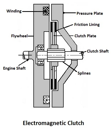
These types of clutches are operated electrically but the torque is transmitted mechanically. This is why this type of clutch is known as an electro-mechanical clutch. Over the years, now it has become an electromagnetic clutch.
These clutches have no mechanical linkage to control their engagement that’s why it provides fast and smooth operation. The electromagnetic clutches are most suitable for remote operation which means you can operate the clutch at a distance.
The clutch has a flywheel consisting of winding. The electricity is supplied by the battery. When the electricity passes through the winding it produces the electromagnetic field which causes it to attract the pressure plate to get engaged. When the electricity supply is cut off the clutch is disengaged.
In this clutch system, the gear lever has a clutch release switch which means when the driver operates the gear lever to change gears the switch is operated cutting off the current supply to the winding which causes the clutch to disengage.
Vacuum clutch
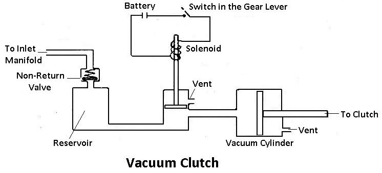
The figure shows the vacuum clutch mechanism. This type of clutch uses the existing vacuum in the engine manifold to operate the clutch. The vacuum clutch consists of a reservoir, non-return valve, vacuum cylinder with piston, and solenoid valve.
Construction and working:
As the figure shows the reservoir is connected to the inlet manifold through a non-return valve. A vacuum cylinder is connected to a reservoir through a solenoid-operated valve. The solenoid is operated from the battery and the circuit has a switch that is attached to the gear lever. The switch is operated when the driver changes the gear by holding the gear lever.
Let’s see how it works. When the throttle is opened the pressure increases in the inlet manifold due to this the
In the normal operation, the solenoid valve rod is in the bottom position of the valve as shown in the figure and the switch in the gear lever remains open. At this stage, the atmospheric pressure acts on both the side of the piston of the vacuum cylinder, because the vacuum cylinder is open to the atmosphere through the vent.
When the driver changes the gear by holding the gear lever the switch gets closed. The solenoid energizes and pulls the valve up this connects one side of the vacuum cylinder to the reservoir. This action opens the passage between the vacuum cylinder and the reservoir. Due to the pressure difference, the vacuum cylinder piston moves forward and backward.
This piston movement is transferred by a linkage to the clutch, causing it to disengage. When the driver is not operating the gear lever, the switch is open the clutch remains engaged due to the force of the springs.
Hydraulic Clutch
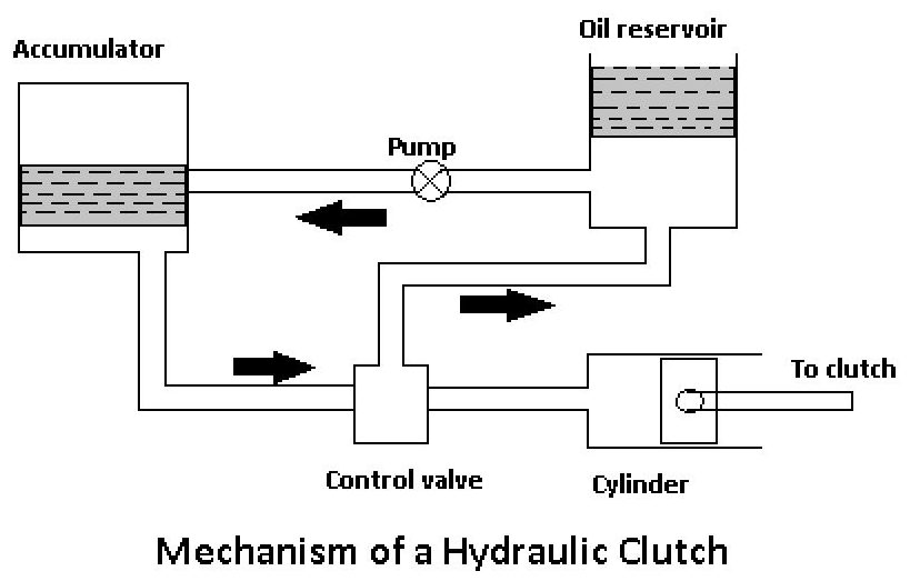
The hydraulic clutch working operation is the same as the vacuum clutch. The major difference between these two is that the hydraulic clutch is operated by oil pressure whereas the vacuum clutch is operated by vacuum.
The figure shows the mechanism of a hydraulic clutch. It has fewer parts than other clutches. It consists of an accumulator, control valve, cylinder with piston, pump, and reservoir.
Working of Hydraulic Clutch
The oil reservoir pumps the oil into the accumulator through a pump. The pump is operated by the engine itself. The accumulator is connected to the cylinder through the control valve. The control valve is controlled by a switch that is attached to the gear lever. The piston is connected to the clutch by a linkage mechanism.
When the driver holds the gear lever to change the gears, the switch opens the control valve allowing the oil under pressure to the cylinder. Due to the oil pressure, the piston moves forward and backward which causes the clutch to get disengaged.
When the driver leaves the gear lever the switch is open which closes the control valve and the clutch will be engaged.
Freewheel Unit
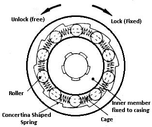
The freewheeling unit clutches are also known as spring clutch, overrunning clutch, or one-way clutch. It is the most important part of every overdrive. The transmission of power is in one direction similar to bicycles. The freewheeling unit is often mounted behind the gearbox.
The power is transmitted from the main shaft to the output shaft by driving the output shaft when the planetary gears are in overdrive. A flywheel unit has a hub and an outer race. The hub has internal splines to connect it to the transmission main shaft.
The outer surface of the hub contains 12 cams so designed to hold 12 rollers in a cage between them and the outer race. The outer race is splined to the overdrive outer shaft.
Working:
When the hub is driven in the clockwise direction, as shown in the figure. The roller rides up the cams, and by their wedging action, they force the outer race to follow the hub. Thus the outer race moves in the same direction and at the same speed as the hub.
When the hub speed slows down, and the outer race is still moving faster than the hub, the rollers move down the cams, releasing the outer race from the hub. Thus the outer race moves independently of the hub and the unit acts as a roller bearing.
The transmission main shaft is connected to the hub and the output shaft is connected to the outer race. Thus freewheel unit can transmit power only from the main shaft to the output shaft.
That’s it. If you like the article on “types of clutches” share it with your friends. If you have any doubts or questions about “types of clutches” leave a comment.
Subscribe to our newsletter to get notification:
Download the free PDF file of this article:
Read more in our blog:
- What are the Types of Car Sensors and Their Functions?
- Different Types of Fuel Injection Systems Explained
- Types of Car Jacks & Their Uses Explained
FAQs
In basic terms, an automobile clutch is a mechanical component that allows for smooth gear changes by connecting and disconnecting the engine’s power from the transmission. This is a crucial part of manual gearboxes since it acts as a bridge between the engine and the wheels.
The car can stop more quickly when the brakes are applied when it is moving at a speed of 100 km/h; still, the clutch must be engaged before the engine stops. When you apply the brakes without engaging the clutch while traveling at 20 km/h in urban traffic, the engine will cut off.
No. It won’t change overall speed because it does not affect aerodynamics or total power.
When a clutch fails to properly engage or disengage the transmission (gear box), the car may slip out of gear or struggle to stay in gear when it accelerates. This is known as clutch slipping.
Thanks a lot engineer, your articles are greatly helpful.
you’re welcome
Very good knowledge provided by you for intrested people who are interested to teach iti students
Thank you so much 🙂
What is a dual mass flywheel..
A dual-mass flywheel is a rotating mechanical device that is used to produces continuous energy in systems where the energy source is not continuous, just as a conventional flywheel works.
Thank you very much for the introduction. But awaiting for a figure of the same which’ll help us more to understand.
You’re welcome.
Nice Post
Thank you
This post help me to learn about clutches. Thanks for this
You’re Welcome 🙂
THANKS A LOT FOR THE INFORMATION.
I’M A FITTING AND TURNING AT ONE OF THE TVET COLLEGES IN SOUTH AFRICA
YOUR INFORMATION HELPED MY STUDENTS AND I A LOT
You’re welcome and keep visiting 🙂
Can you list the vehicle name
Sure! in a new article 😉
Good one
Thanks 🙂
Nice
Thank you 🙂