Hello readers! In this post, we’ll discuss what is a logic gate? and the different types of logic gates with truth table using illustrations.
You can also download the PDF file of this article at the end.
Without further ado, let’s begin discussing what is a logic gate.
What are Logic Gates?
Logic gates are the primary building blocks of any type of digital system. It is an electronic circuit that consists of more than one input voltage and only one output.
The relation between input and output depends on a fixed logic. Based on this, logic gates are called AND gate, OR gate, NOT gate, etc.
The interaction of gates to do different types of logical operations is called logic design. A truth table lists possible combinations of inputs and similar outputs. All logic gates follow their truth table.
Digital logic gates are made to form RTL (resistor-transistor logic) or DTL (diode-transistor logic) circuits from discrete parts such as resistors, transistors, and diodes.
The most “standard” personal digital logic gates along with their respective truth tables are described below.
Read Also: Different Types of Capacitors
Types of Logic Gates
Following are the standard types of logic gates with truth table, which are described below:
- According to the standard types of logic gates
- AND gate
- OR gate
- According to the inverting types of logic gates
- NAND gate
- NOR gate
- According to the exclusive type of logic gates
- Exclusive – OR gate (Ex-OR gate)
- Exclusive – NOR gate (Ex-NOR gate)
- According to the single input type of logic gates
- Hex buffer
- NOT gate (Inverter)
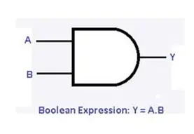
#1 AND Gate
The AND gate is often called an “all-or-nothing gate”. The AND gate consists of 2 or more input signals. It allows only 1 output when the input is 1. Unless it gives 0 output. In one word, it produces 0 output when the input is 0.
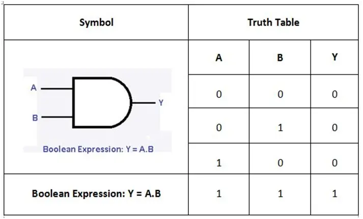
The AND gate corresponds to the work of series switches for the input. The table above shows the symbol and truth table. An AND gate diagram is shown in Fig which shows the idea of using switches in the AND gate.
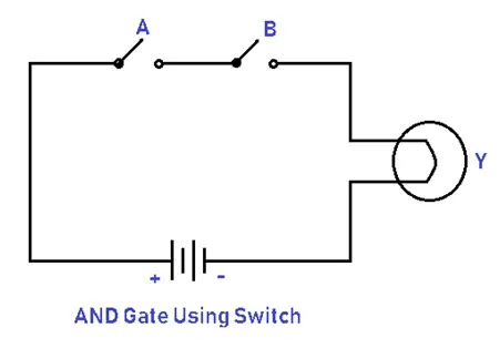
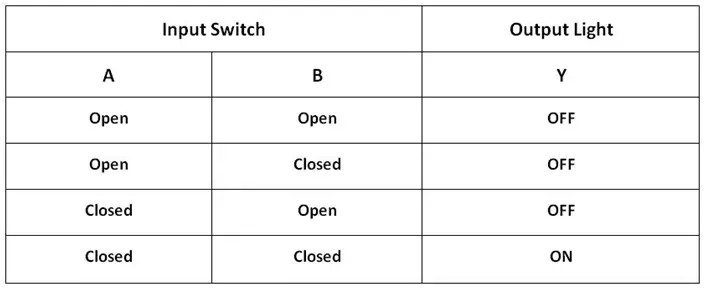
The lamp (Y) indicates light only when both input switches (A and B) are closed or off. The below table above the other possible combinations for switches A and B. The below table shows all possible combinations of the switch.
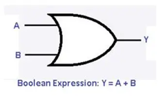
#2 OR Gate
The OR consists of 2 or more input signals. An OR gate is often called an “any or all gate”. It provides 1 output or all inputs are 1. In other words, It provides 0 output when the input is 0.
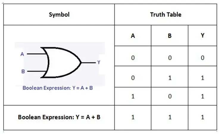
The OR gate corresponds to the action of parallel switches for the input. The table above shows the symbol and truth table. An OR gate diagram is shown in Fig which shows the idea of using switches in the OR gate.
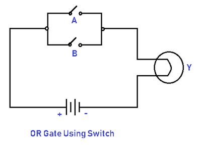
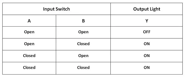
The lamp (Y) indicates to light when either switch A or switch B is closed or off. The table below shows the other possible combinations for switches A and B. Below shows all possible combinations of the switch.
Read Also: What are the Types of Insulators?
#3 NAND Gate
The NAND gate expresses an AND gate and is followed by an inverter. It consists of 2 or more input signals. This provides 0 output only when the input is 1. It provides 1 output when the input is 0.
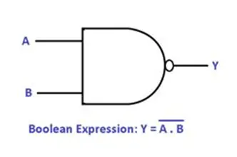
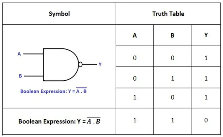
The British mathematician De Mergen’s second theory says that the NAND gate is similar to a negative (bubbling) OR gate. The table above shows the symbol and truth table of the NAND gate.
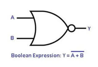
#4 NOR Gate
The NOR gate expresses an OR gate developed by an inverter. NOR gate consists of 2 or more input signals. It provides a 1 when the input is 0. It provides 0 output when the input is 1.
The NOR gate expresses an OR gate developed by an inverter. NOR gate consists of 2 or more input signals. It provides a 1 when the input is 0. It provides 0 output when the input is 1.
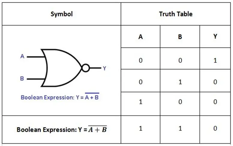
Hence, it also acts as a negative (bubbled) AND gate. The table above shows the symbol and truth table of the NOR gate.
Read Also: Different Types of AC Motos and Their Uses
#5 Exclusive – OR Gate (Ex-OR Gate)
The Exclusive-OR (Ex-OR) gate is often called an anti-coincidence gate. It provides only 1 output when an odd number of 1 is present.
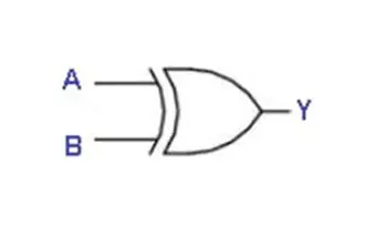
It only provides 1 output when two inputs are not equal when one input is 1 or 0. The Ex-NOR gate can be used as a controlled inverter that connects an input terminal to logic 1 and feeds the signal to be inverted with the other terminal.
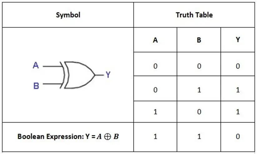
A two-input X-OR gate is an inequality detector. The table above shows the symbol and truth table of the Ex-OR gate.
#6 Exclusive – NOR Gate (Ex-NOR Gate)
The Exclusive-NOR (Ex-NOR) gate is also called a combination gate. Ex-NOR gate provides 1 output only when many 1 is present.
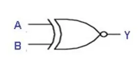
It provides only 1 output when two inputs are equal it means both inputs are 1 or 0. The Ex-NOR gate is used as a controlled inverter by combining one input terminal to logic 0 and feeding the signal to be inverted with the other terminal.
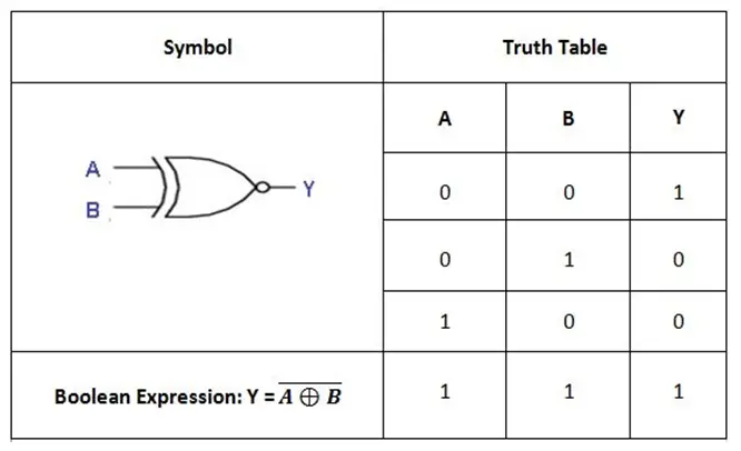
A two-input X-NOR gate is an equality detector. The table above shows the symbol and truth table of the Ex-NOR gate.
Read Also: What is a DC Motor? How it works?
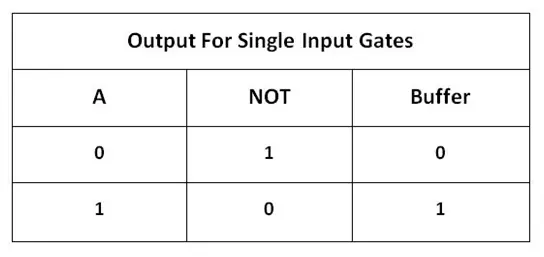
#7 Hex Buffer
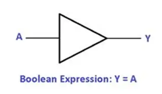
The Hex buffer is shown in Fig. It provides 1 output when the input is 1. Similarly, it provides 0 output when the input is 0 which means nothing.
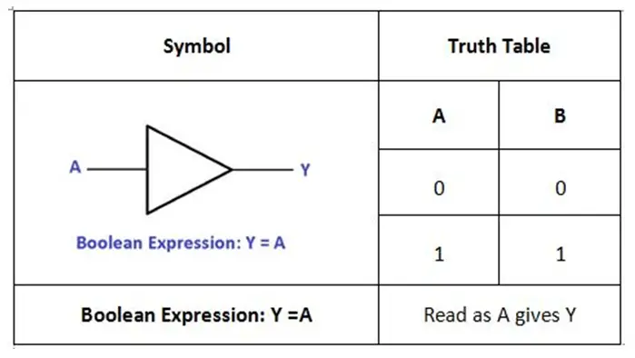
The above table shows the symbol and truth table with the boolean expression for the hex buffer.
#8 NOT Gate (Inverter)
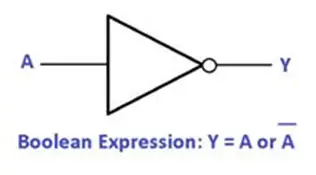
The NOT gate with inverter is shown in Fig. This provides 1 output when the input is 0. Similarly, it provides 0 output when the input is 1.
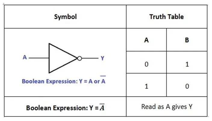
The above table shows the symbol and truth table with the boolean expression for the NOT gate (inverter).
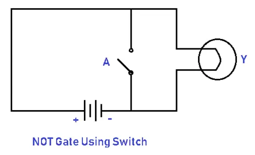
The status of two possible switches is given below. If the input switch is open then the light will be ON. If the input switch is closed then the light will OFF.
Read Also: 16 Different Types of Transformers
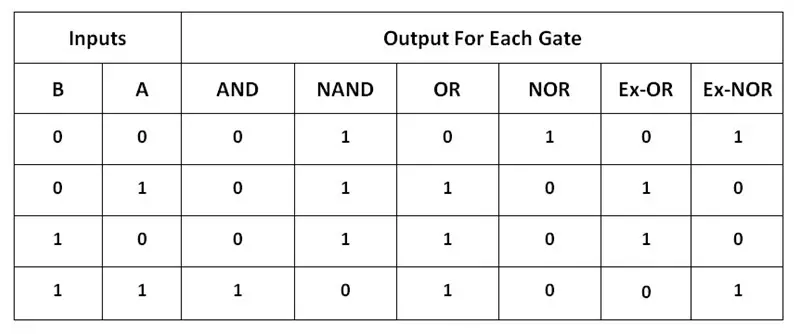
Quick Summary of All Logic Gates with Truth Table
The following logic gates truth table relates the logic uses of a 2-input logic gate as described above:
Applications of Logic Gate
There are many uses for logic gates, but they are mostly determined by their truth table or mode of operation. Many electronic devices use logic gates, including safety thermostats, push-button locks, automatic watering systems, and burglar alarms activated by light.
One main advantage is that, if the operations are improved, basic logic gates can be employed in a variety of ways. Additionally, the amount of gates that can be utilized in a single device is unlimited.
However, it may be limited due to the device’s physical space. Logic gate area unit arrays are found in digital integrated circuits (ICs).
Read Also: Types of Electric Motors & Their Working
De Morgan’s Theorem
DeMorgan’s Theorems are essentially two sets of laws or rules derived from the AND, OR, and NOT Boolean expressions utilizing two input variables, A and B. These two theorems or rules enable the input variables to be negated and transformed from one Boolean function form to the other.
The De Morgan Theorem consists of two theorems.
#1 The First Theorem
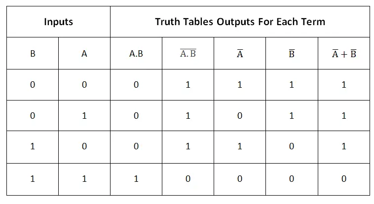
According to De Morgan’s First Theorem, when two (or more) input variables are AND’ed and negated, the results are equivalent to the OR of the complements. This means that a negative-OR function is the equivalent of the NAND function, demonstrating that,
DeMorgan’s First Theorem using Truth Table
Using Logic Gates to Implement DeMorgan’s First Law
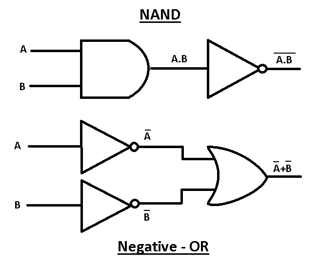
A conventional NAND gate with inputs A and B can be used to implement Ā.B̅. After the two inputs are inverted, Ā and B̅ are produced by the lower logic gate arrangement. After that, these serve as the OR gate’s inputs. As a result, the OR gate’s output is Ā+B̅.
Hence, it is evident that a NAND gate function is equal to a normal OR gate function that has inverters (NOT gates) on each of its inputs. This means an individual NAND gate is equivalent to a negative-OR gate.
#2 The Second Theorem
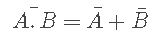
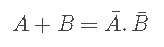
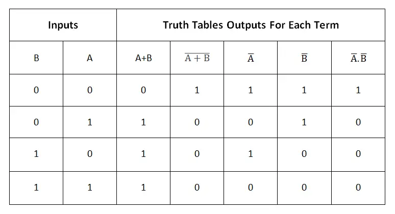
In DeMorgan’s Second Theorem, when two (or more) input variables are OR’ed and negated, they are equivalent to the AND of their complements. As a result, the NOR function is equivalent to a negative-AND function, proving that Ā+B̅ = Ā.B̅, and once again, we can demonstrate this by using the truth table.
DeMorgan’s Second Theorem using Truth Table
Using inputs A and B, a normal NOR gate function can be used to implement A+B.
Logic Gates to Implement DeMorgan’s Second Law
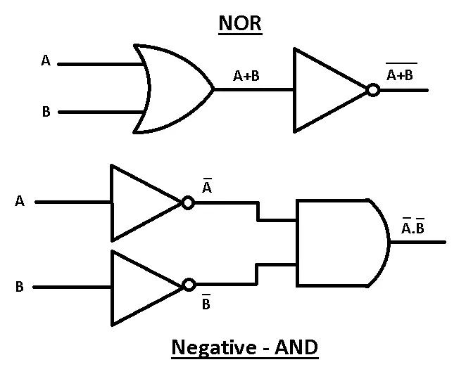
Using inputs A and B, a normal NOR gate function can be used to implement Ā+B̅. Before producing Ā and B̅, the two inputs are inverted in the lower logic gate arrangement. Thus, the AND gate’s inputs are formed. As a result, the AND gate’s output is A.B.
By combining an AND gate function with an inverter (NOT gate) on each input, we can see that the output condition of each AND gate is equivalent to that of a NOR gate, and thus the equivalency of a NOR gate to a negative AND can be represented in this way.
Final Thought
That’s it. Thanks for reading. I hope I have covered everything about the “Types of Logic Gates.” It would be helpful if you could let me know if there was anything I missed or if you have any doubts about anything I wrote.
Please share this article with your friends if you find it interesting.
Want free PDFs direct to your inbox? Then subscribe to our newsletter.
Download PDF of this Article:
You might want to read the following articles:
- What Are The Different Types of Circuit Breakers?
- Different Types of Batteries and Their Applications
- What Are The Essential Electrician Tools? [Names & Uses]
External Links: