In this article, you’ll learn What is Facing Operation? Its Definition, Process, Face Milling Operation, and Procedure are all explained with pictures.
You can also download the PDF file of this article at the end.
What is Facing?
Facing is a lathe machining operation in which material is removed from a workpiece’s end using a particular tool. It produces a smooth surface perpendicular to the rotation axis of the workpiece. In machining, facing can be used in two different ways: on a milling machine and on a lathe.
The facing operation on a milling machine includes various milling operations but mainly considers face milling. Whereas in lathe machines, facing operation is generally used in turning and boring operations.
Let’s understand the facing operation in detail below.
Read Also: What is Turning Operation? [Definition, Types & Procedure]
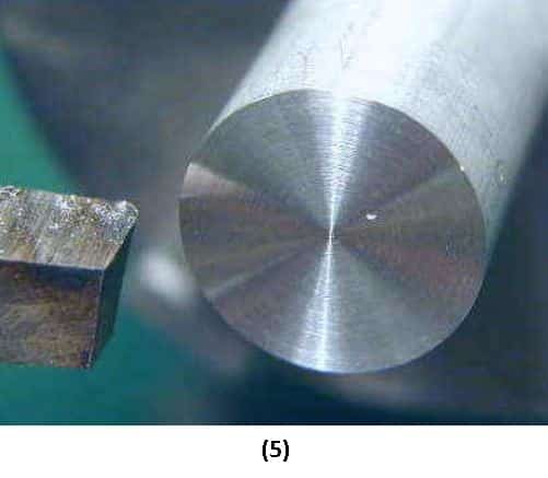
Facing Operation on Lathe
When performing a facing operation on a lathe, the machinist uses a facing tool to remove a flat surface perpendicular to the workpiece’s rotational axis. A facing tool is usually mounted in a tool holder that is installed on the lathe machine.
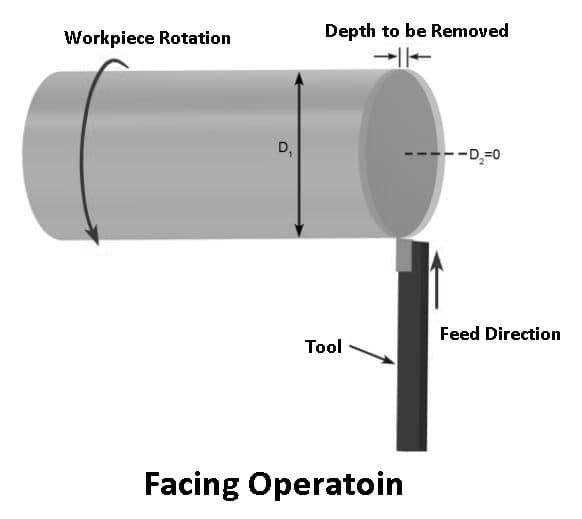
The facing tool is then fed perpendicularly across the axis to the workpiece. The machinist will have the option of using hand feed or power feed option in the machine. To obtain a smooth surface, it is optimal to use the power feed option due to the constant feed rate.
By facing, the workpiece will be cut to its finished length very precisely. Depending on how much material must be removed from the workpiece, a machinist may take roughing or finishing cuts.
Many factors can affect the quality and performance of facing operations in lathe machines, including:
- What kind of material is the workpiece made of
- Cutting tool size and material hardness
- Workpiece holding methods
- Speed of rotation
- how the part is being clamped
Read Also: Understand Types of Lathe Cutting Tools Used in Lathe
Face Milling Operation on Milling Machine
Face milling is the process of cutting a flat surface perpendicular to the milling cutter’s axes. In this process, the material is removed by rotating the tool in a counterclockwise direction as the table feeds the workpiece across the cutter.

Face milling operations can be accomplished in both manual and CNC machining. It’s best to let the machine feed the table to get a smooth surface finish. Some models of manual and CNC milling machines will have this option, but older milling machines will don’t.
With the help of this feature, the machinist must use a machine feed instead of a manual feed. This will give in an optimum surface finish due to the continuous feed maintained by the mill. Feeding the table by hand will result in human error in the process.
In addition, machinists also have the option of taking roughing cuts and finishing cuts in face milling.
Many factors can affect the quality and effectiveness of facing operations in milling, including:
- Feeding
- Cutting tool size
- material hardness
- Speed of rotation
- how the part is being clamped
Difference Between Lathe Facing and Milling Facing
| Lathe Facing | Milling Facing |
|---|---|
| Lathe facing operation can be done using the lathe machine. | Whereas milling facing can be done using the milling machine. |
| In the lathe facing, the part is moving, and the cutting tool is stationary. | Milling facing involves the facing tool rotating against the fixed workpiece. |
| A machinist can face a cylindrical-shaped workpiece in a lathe facing. | Whereas in milling facing, the machinist may be faced with rectangular or odd-shaped materials to form parts into cubes and other non-cylindrical shapes. |
| Lathe facing is a type of turning operation that involves boring, grooving, reaming, and more. | Milling facing is working opposite to turning. |
Read Also: What is Honing Machine? Types, Operations & Uses
How To Perform Facing Operation on Lathe?
Before starting the machine, move the tool’s tip until it touches the end of the workpiece with the compound handwheel. By turning the cross-feed crank back, the tool will go beyond the workpiece’s diameter.
Now, turn on the lathe and adjust the speed to a few hundred RPM with the speed control knob. When the machine is on, slowly push the cross-feed handwheel to move the tool toward the workpiece.
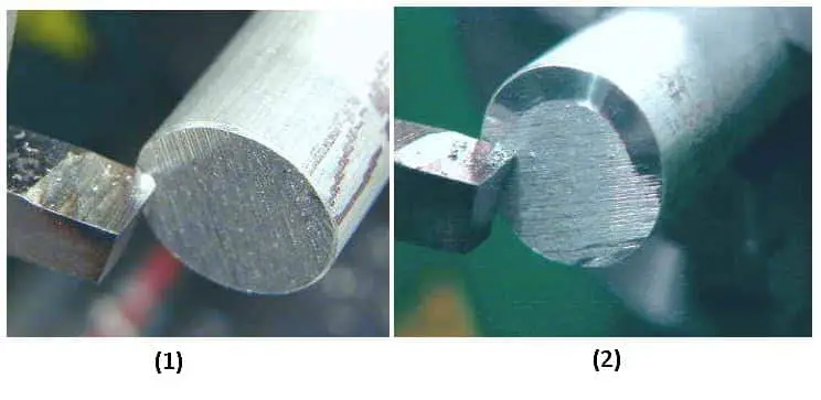
As soon as the tool touches the workpiece, it will begin to remove the metal from the end. Once the tool reaches the center of the workpiece, crank it in the opposite direction (towards you) until it comes back from the edge.
Read Also: What are the Different Types of Grinding Machines?
#1 Rough Cutting
The tool should be run by about .010″ (ten thousandths of an inch) using the compound crank. If the compound on the cross slide is set to 90°, each division you rotate the crank will move .001 (one-thousandth of an inch) toward the tool chuck.
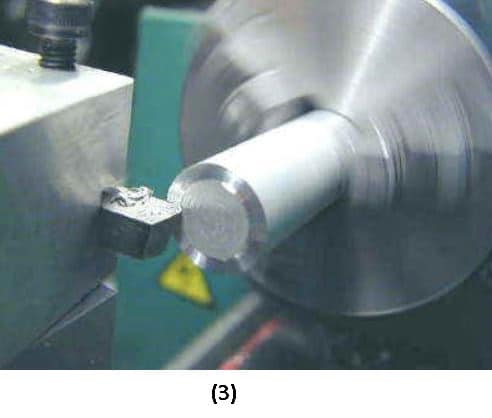
If the compound is set to any other angle on the cross slide, consider 30°, it will move the tool by less than .001 for each division. In order to calculate the exact amount, we need to know the trigonometric sine of the angle.
If the sine of 30 degrees is .5, then the tool will advance .0005 (half of one one-thousandth inch) per division. The figure below shows you the first pass of the facing operation, in which about .010″ of metal is removed.
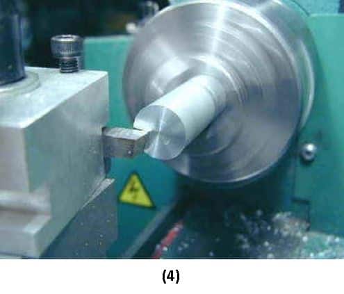
#2 Return Pass
If you crank the tool backward after reaching the center of the workpiece, you may notice that it removes a small amount of metal on the return pass. This is because the surface is not perfectly smooth and this is removing metal from high spots.
During a return cut, you can remove a lot of metal by moving the tool in a small way into the workpiece on the return pass. Since the tool must descend into the face of the workpiece, it works best with a fairly sharp pointed tool.
#3 Finishing Cut
It may take three or more passes to get a nice smooth finish across the face of your workpiece, depending on how rough the end was, to begin with. These initial passes are called roughing passes and cut relatively large amounts of metal.
When a pretty smooth surface is achieved, you can make a final finishing cut of approximately .001 to .003″ of metal and obtain a more excellent smooth surface. The finishing cut can also be made at a higher RPM to achieve a smoother finish.
Read Also: What are Different Shaper Machine Operations?
Are Facing and Turning Operations Same?
The only difference is that in the turning operation, you can reduce the diameter of the workpiece, while in the facing operation, you can reduce the length of the workpiece.
In machining, turning refers to any operation in which a stationary cutting tool is applied against a rotating workpiece to remove material. As a result, lathe facing is also a type of turning operation.
However, turning operations do not only involve facing. Also included are operations that involve the use of a lathe, such as parting, groove-making, boring, knurling, and threading. Generally, turning is classified as tapered turning, spherical turning, or hard turning.
Facing Operation in CNC
Through CNC Facing, the material is removed from the end of a workpiece on a perpendicular angle to the rotational axis of the workpiece using a special tool. For better understanding, I have explained a program for facing operations. This will give you an idea of how facing is done on a CNC lathe.
Program
O0001(Facing)
N1;
T0;
G40;
G28 U0 W0; -(X-U,Z-W)
G54;
G92 S1000;
G95 F0.2 T0101;
G96 S280 M04;
G00 Z5.0;
G00 X82.0;
G01 Z2.0 ;
G01 X0.0;
G1 Z3.0;
G00 X82.0;
G01 Z0.0;
G01 X0.0;
G1 Z1.0;
G00 X200.0;
T0;
G28 V0 W0;
M01;
M30;
Program Explanation
| CNC Code | Meaning |
|---|---|
| N1 | Sequence number |
| T0 | Tool wear cancel |
| G40 | Cancelling G41 & G42 |
| G28 U0 W0; -(X-U,Z-W) | Home position |
| G54 | Work Coordinate |
| G92 S1000 | Speed |
| G95 F0.2 T0101 | Feed & Tool |
| G96 S250 M04 | Cutting speed & spindle rotation |
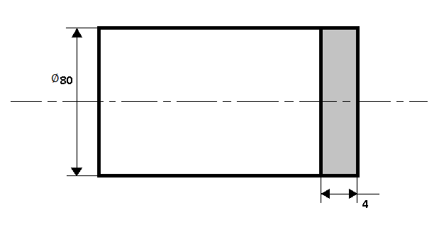
| G00 Z5.0 | Tool movement to Z5.0 rapidly. As the Work coordinate is set to Z0.0 at the final face, Z5.0 is the safety distance. That is, the raw material is 4.0 more than the final face, which needs to be faced. Assuming Z0.0 at a raw material face, we must face -4.0. |
| G00 X82.0 | Tool movement to X82.0 rapidly. It is the safety distance for the x-axis. |
| G01 Z2.0 | Tool movement for Z2.0. This distance has to be faced. |
| G01 X0.0 | Tool movement for X0.0 in feed. This will remove 2mm of material. |
| G1 Z3.0 | Safety distance in Z3.0 |
| G00 X82.0 | Tool movement to safety distance in X82.0 |
| G01 Z0.0 | Tool movement for Z0.0, which is the end face set in G54. A further 2mm must be faced with this movement. |
| G01 X0.0 | This will remove another 2mm. Facing is done. |
| G01 Z1.0 | Tool movement to safety distance in the Z-axis. |
| G00 X200.0 | Tool movement to safety distance in the X200.0 |
| T0 | Cancel tool wear |
| G28 V0 W0 | Home position |
| M01 | Optional stop |
| M30 | Program stop |
Closing It Up
That’s it. Thanks for reading. I hope I have covered everything about this topic. If I missed something, or if you have any doubts, let me know in the comments. If you liked this article, please share it with your friends.
Want free PDFs direct to your inbox? Then subscribe to our newsletter.
Download PDF of this article:
You might like to read more articles in our blog: