In this article, you’ll learn What is Turning Operation? Its Definition, Process, Types, Cutting Parameters, Procedure, and Dynamics are all explained with pictures.
What is Turning?
Turning is a machining process performed on a machine in which the cutting tool (non-rotary tool bit) follows a helix tool path by moving linearly along the workpiece.
Turning traditionally refers to the action of cutting external surfaces, whereas “boring” refers to the action of cutting internal surfaces (holes). Thus, the phrase “turning and boring” classifies several processes known as lathing.
Turning can be done manually, as in the traditional form of the lathe, which often requires constant supervision by the operator. An automated lathe that doesn’t require operator input and is most commonly referred to as a computer numerical control, or CNC.
An object that undergoes turning operations is called a “turn part” or a “machined object.” It is possible to process most cylindrical, conical, endfaces, grooves, and thread surfaces that have rotary surfaces with turning operations. Let’s understand the process of turning.
Related: 22 Types of Lathe Machine Operations and Their Applications
Turning Process
In the turning process, the tool normally moves with the main axis (z) while the workpiece rotates. When configured with a diameter less than the actual diameter of the workpiece, it cuts off the workpiece’s “surface” and reduces its diameter.
It can also run perpendicular to the central axis. This operation is typically used to remove material only from the flat face (facing operation) or to remove a specific portion from the total length (cut-off).
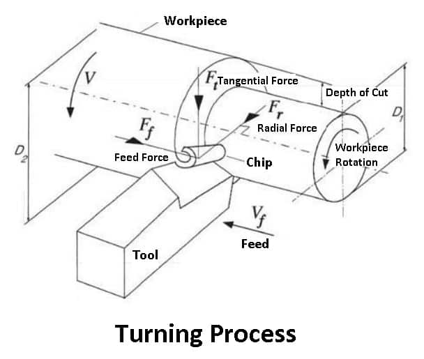
The figure above illustrates the standard turning process forces, which can also be seen given the parallel direction of the cutting tool and the spindle’s velocity.
There are a few things to consider when a good accuracy and surface finish are required. Good operating quality, clamping stability, and correct center height is three of these important factors.
It is assumed that the chip generated during turning slides on the tool’s rake face. As positive rake angles produce higher shear angles, cutting forces are reduced, and chips flow more easily, resulting in a better surface finish.
Read Also: What is Twist Drill? Its Working, Types, and Nomenclature
Turning Operation
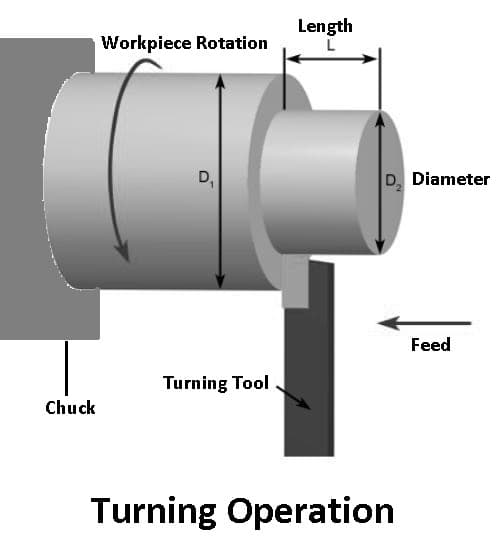
When turning, the workpiece is rotated, and a cutting tool is rotated along 1, 2, or 3 axes of motion to produce precise diameters and depths. The main purpose of turning is to reduce the diameter of the workpiece to the required dimension.
The turning can be done either outside or inside the cylinder to produce tubular components for various geometries. In the tuning operation, the diameter must be cut to size in two cuts: roughness and finishing. For the workpiece to have the same diameter at both ends, the lathe’s center must be aligned.
In rough turning operations, excess material is removed in order to achieve a predefined thickness while disregarding surface finish and accuracy. With Finish turning, the workpiece is produced with final accurate dimensions and a smooth surface finish.
What is a Rough Turning?
These operations are performed on a lathe and are used to remove as much metal as possible in the shortest possible time. Precision and surface finish is not important in this type of turning operation.
Accordingly, a maximum depth of 0.030 inches and a feed of 0.020 to 0.030 inches are usually recommended. The workpiece is typically roughened into as many cuts as possible within approximately 0.030″ of the finished size.
What is a Finish Turning?
Finish turning is performed on a lathe and, followed by rough turning, produces a smooth surface finish, and cuts the workpiece to a precise shape.
The type of surface finish produced is affected by a few factors, such as the position of the cutting tip, the hardness of the machine and workpiece, and the speed and feed rate of the lathe.
Read Also: Different Types of Lathe Machine and Their Working
Types of Turning Operation
The turning process can be of various types, such as straight turning, taper turning, profiling, or external grooving. In general, single-point cutting tools are generally used to perform turning operations. Let’s discuss the types of turning operations.
- Plain turning
- Step turning
- Taper turning
- Chamfer turning
- Contour turning
- Spherical generation
- Hard turning
- Eccentric turning
#1 Plain Turning
During plain turning, excess material is removed from a cylindrical workpiece’s surface. This operation involves holding the work in a chuck or between centers, then driving the tool longitudinally by hand or with a motor.
#2 Step Turning
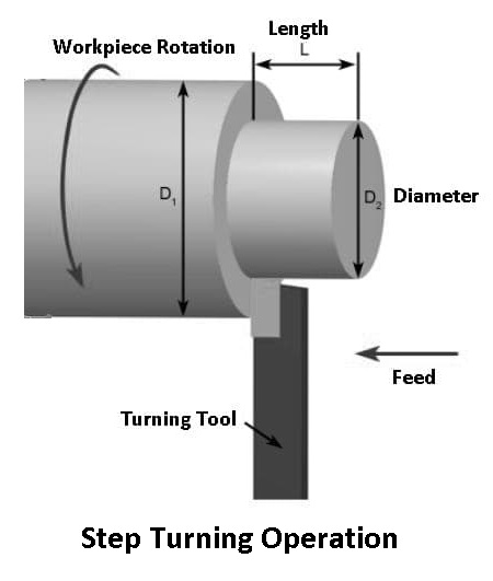
Step turning is a turning operation in which a series of steps of different diameters are produced on a workpiece. The final feature of the workpiece forms a step.
#3 Taper Turning
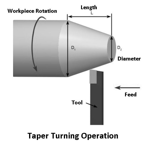
The taper-turning operation is a gradual reduction in diameter from one end of a cylindrical workpiece to another. This can be achieved using a composite slide, taper-turning attachment, and offsetting of the tailstock on a lathe.
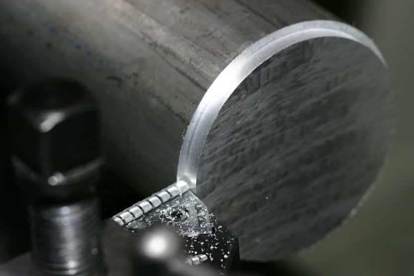
#4 Chamfer Turning
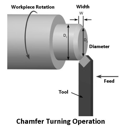
Chamfering is similar to step turning in that it is the process of beveling the extreme end of the workpiece. This is a necessary operation after thread cutting so that the nut can freely slide over the threaded workpiece. Chamfering also eliminates sharp edges, greatly reducing the chance of cuts.
#5 Contour Turning
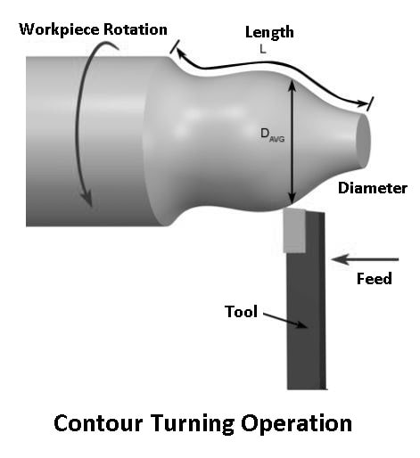
In the type of turning operation, the cutting tool follows an axial path with a predetermined geometry. To create desired contours in a workpiece, multiple passes of a contouring tool are required. It is possible, though, to produce the same contour shape using form tools in a single pass.
#6 Spherical Generation
Spherical generation produces a finished surface by turning a form around a fixed axis of revolution. To do this, the user must use a hydraulic copy attachment with a form tool on the CNC lathe.
#7 Hard Turning
The term “hard turning” refers to turning materials with a Rockwell hardness of over 45. This is usually done after heat treatment of the workpiece. The process is primarily intended to replace traditional grinding operations.
When applied to stock removal only, hard turning outperforms rough grinding. However, grinding is preferable when it is applied for finishing where form and dimensions are essential. By using grinding, high dimensional accuracy of roundness and cylindricity can be produced.
#8 Eccentric Turning
Excentric turning is the process of machining a cylindrical surface with two axes of rotation, one of which is offset from the other. In this operation, three sets of center holes are drilled here. A machining operation can be carried out on each surface of the workpiece by holding it at these three centers.
Read Also: Different Types of Lathe Attachments and Accessories
Dynamics of Turning Operation
The dynamics of the tuning process can be defined in three categories, which are as follows:
- Forces
- Speed
- Feed
#1 Forces
In a turning operation, relative forces are crucial in the design of machine tools. These forces should be able to be absorbed by the machine tool without causing significant deflections, vibrations, or chatter.
The following are the three major forces during a turning process:
- Cutting or tangential force: These forces act downward on the tooltip, causing the workpiece to be deflected upwards. These are essential as it supplies the energy required for the cutting operation.
- Axial or feed force: This force operates in the longitudinal direction. It is also known as feed force because it is applied in the feed direction of the equipment. As a result, the tool is forced away from the lathe chuck due to this force.
- Radial or thrust force: It acts in a radial direction and pushes the tool away from the workpiece.
#2 Speed
For turning operation, the speed is selected based on the cutter material, workpiece material, setup hardness, machine tool rigidity and spindle power, coolant choice, and other factors.
#3 Feed
Feed is the distance that the tool moves through the material in one revolution and is specified as mm per revolution (mm/rev).
Cutting Parameters in Turning Operation
The cutting tool speed and turning speed are specified by means of several parameters. Depending on the workpiece material, tool material, tool size, and more, these parameters are selected for each operation.
- Cutting feed
- Cutting speed
- Spindle speed
- Feed rate
- Axial depth of cut
- Radial depth of cut
#1 Cutting Feed
Cutting feed is the distance that the cutting tool or workpiece moves during one revolution of the spindle and is usually measured in inches per revolution (IPR). The cutting feed is also equal to the feed per tooth For a multi-point tool and is measured in inches per tooth (IPT).
#2 Cutting Speed
It is measured in surface feet per minute (SFM), the cutting speed of the workpiece surface as it relates to the edges of the cutting tool.
#3 Spindle Speed
This is the rotational speed of the spindle and workpiece in revolutions per minute (RPM). Spindle speed is calculated by dividing the cutting speed by the circumference of the workpiece.
#4 Feed Rate
This is the speed of movement of the cutting tool relative to the workpiece as the tool cuts and is measured in inches per minute (IPM).
#5 Axial Depth of Cut
The depth of the tool along the axis of the workpiece as it cuts in a facing operation. A larger axial depth of cut will require a lower feed rate. Otherwise, it will result in a greater tool load and reduced tool life.
#6 Radial Depth of Cut
The depth of the tool varies with the radius of the workpiece as it cuts in a turning or boring operation. It is important to use a low feed rate when cutting large radial depths. Otherwise, the tool will be under an excessive amount of load, resulting in a shorter tool life.
Read Also: What is Cutting Speed, Feed, Depth of Cut, and Machining Time in Lathe?
Procedure to Exact Depth of Cut
To determine the exact depth of the cut, follow the steps below:
- The user should set the compound rest to 30 degrees.
- After that, attach the roughing or finishing tool. If you are feeding the saddle toward the headstock, use a right-hand turning tool.
- Now, you should move the tool holder to the left side of the compound support and set the tool head in the center of the right height.
- Once the tool head is fixed, set the lathe to the correct speed and feed the diameter as well as the type of material to be cut.
- Start the lathe and go to the right-hand end of the workpiece with a slight cut about 0.005″ and 0.250″ long.
- Now stop the lathe, but do not move the handle of the infeed screw.
- Rotate the carriage handwheel to move the tool to the end of the workpiece (in the right direction).
- Before cutting, measure the workpiece and calculate the amount of material to be removed.
- Turn the scale ring over half the amount of material to be removed. As an example, if 0.060 inches is needed to be removed, the scale ring should be turned in by 0.030 inches.
- The diameter of the blank is reduced by two thousandths for every thousandth of the cutting depth.
- After getting the desired diameter of the workpiece, take back the tool post and turn OFF the machine.
Read Also: What is the Difference between NC, CNC and DNC Machine?
Turning Operation in CNC
The CNC Turning process involves holding a bar of material in a chuck and rotating it while a tool removes material from the piece. It is mainly used to make parts that are cylindrical in nature.
To better understand how to perform turning on a CNC lathe, I have given an example of Turning-CNC Programming below. This is the most basic example of turning operation programming. From the below example, beginners can get complete information about turning operations in CNC.
Program
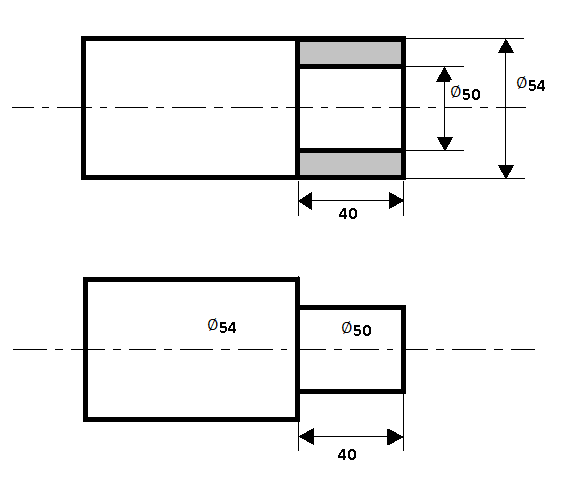
O0001(For Plain Turning);
N1;
T0;
G40;
G30 P3 U0 W0;
G54;
G92 S1000;
G95 F0.2 T0101;
G96 S250 M04;
G00 Z3.0;
G00 X56.0;
G01 X50.0 M08;
G01 Z-40.0;
G1 X56.0;
G00 X200 M09;
T0;
G28 U0 W0;
M01;
M30;
Program Explanation
| CNC Code | Meaning |
|---|---|
| N1 | Sequence number |
| T0 | Tool wear cancel |
| G40 | Cancelling G41 & G42 |
| G30 P3 U0 W0 | Rest or Home Position P3-position, U=X axis, W=Y axis |
| G54 | Work Coordinate |
| G92 S1000 | Speed |
| G95 F0.2 T0101 | Feed & Tool |
| G96 S250 M04 | Cutting speed & spindle rotation |
| G00 Z3.0 | Safety distance for the Z axis Tool movement (feed) to Z3.0 Tool will stop at distance of 3.0 from face |
| G00 X56.0 | Safety distance for the X axis Tool movement (feed) to 56 diameter Since the raw material is 54 in diameter. |
| G01 X50.0 M08 | Tool movement (feed) to 50 diameter. M08- Coolant ON. |
| G01 Z-40.0 | turning movement of tool up to Z-40.0 according to drawing. |
| G01 X56.0 | Tool back to safety postion with feed. |
| G00 X200 M09 | Tool move to safety distance of 200 dia. M09- Coolant OFF. |
| T0 | cancelation of tool wear |
| G30 P3 U0 W0 | Home position P3-position, U=X axis, W=Y axis |
| M01 | Optional stop |
| M30 | Program stop and recycle |
Closing It Up
That’s it. Thanks for reading. I hope I have covered everything about the “Turning Operation.” If I missed something, or if you have any doubts, let me know in the comments. If you liked this article, please share it with your friends.
Want free PDFs direct to your inbox? Then subscribe to our newsletter.
Download PDF of this article:
You might like to read more in our blog: