In this article, you’ll learn what is electric discharge machining? Its Working Principle, Advantages, and Applications are explained with pictures.
This article also includes a PDF file that you can download at the end.
Electric Discharge Machining
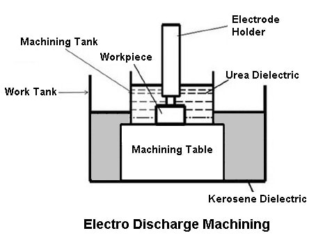
Electric discharge machining, also known as spark erosion, electro-erosion or spark machining, is a process of metal removal based on the principle of erosion of metals by an interrupted electric spark discharge between the electrode tool cathode and the working anode.
Fundamentally, the electric erosion effect is understood by the breakdown of electrode material accompanying any form of electric discharge.
The discharge is usually through a gas, liquid, or in some cases, through solids. A necessary condition for producing discharge is ionization of the dielectric, i.e., splitting up of its molecules into ions and electrons.
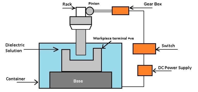
The main components are the electric power supply, the dielectric medium, the workpiece and the tool, and the servo control.
Read Also: What are the Different Types of Welding Machines?
Working Principle of Electric Discharge Machining
- The workpiece and the tool are electrically connected to dc electric power. The workpiece is connected to the +ve terminal. It becomes the anode. The tool is the cathode.
- A gap, known as the ‘spark gap’ in the ranges of 0.005 to 0.05 mm is maintained between the workpiece and the tool.
- When a suitable voltage in the range of 50 to 450 V is applied, the dielectric breaks down and electrons are emitted from the cathode, and the gap is ionized.
- In fact, a small ionized fluid column is formed owing to the formation of an avalanche of electrons in the spark gap where the process of ionization collision takes place.
- When more electrons collect in the gap the resistance drops, causing the electric spark to jump between the workpiece and the tool.
- Each electric discharge causes a stream of electrons to move with a high velocity and acceleration from the cathode towards the anode and creates compression shock waves on both electrode surface.
- The formation of compression shock waves produces a rise in temperature. However, the temperature of the spot hit by the electrons is of the order of 10,000 °C.
- The forces of electric and magnetic fields caused by the spark produce a tensile force and tear off particles of molten and softened metal from this spot on the workpiece.
A part of the metal may vaporize and fill up the gap. The metal is thus removed in this way from the workpiece. The electric and magnetic fields on the heated metal cause a compressive force to act on the cathodic tool so that metal removal from the tool is slower than that from the workpiece.
Read also:
Spark Generator
The spark-generating circuit may be one of the following types:
- Relaxation
- Pulse-generator
The spark generator supplies current to a condenser, the discharge from which produces the spark. The workpiece alternatively becomes a positive electrode (anode) or negative electrode (cathode), respectively. On each reversal of polarity, the tool is eroded more than the workpiece. Hence, the tool wear is greater with this type of arrangement.
The introduction of pulse generators has overcome the drawbacks of relaxation generators. Pulse generators are available, fitted with transistorized pulse-generator circuits in which reverse pulses are eliminated. These generators consist of electronic switching units which let the current pass periodically.
Modern pulse generators possess the means of accurate control over discharge duration, pause time, and current. These factors determine the overcut and hence the accuracy and surface finish. The tool wear is also greatly reduced.
Read Also: Types of Circuit Breakers: Their Advantages & Disadvantages
Overcut
The shape of the area of the cavity produced in the workpiece should theoretically be the same as that of the tool. This, however, is not exactly true because of the overcut. Overcut is the distance the spark will penetrate the workpiece from the tool and remove metal from the workpiece.
Theoretically, it is slightly larger than the gap between the end of the tool and the workpiece. The overcut is generally 0.025 to 0.2 mm, on all surfaces. Overcut causes internal corners on the workpiece to have fillets with radii equal to the overcut.
Another effect of overcutting is to cause the radius of the cavity in the workpiece to be slightly larger than the corresponding radius of the tool nose and also to cause the radius of projection on the workpiece to be slightly lesser than the radius of the cavity of the tool.
This overcut is a function of the voltage of the spark. The overcut increases with higher current and decreases with higher frequency.
Read Also: Types of Insulators Used In Power Transmission Lines
The Electrode (Tool)
The shape of the tool is the same as that of the product desired, except that an allowance is made for side clearance and overcut. For broaching small holes, solid rods may be used, but for larger ones, hollow tools are preferred.
If an object has a geometrical shape or is having symmetry about some axis, a tool equal to only a part of the object will be sufficient for the complete machining of the object. Such segmented tools are especially useful for machining complex shapes that do not require close accuracy.
It is convenient to use a series of simpler tools to produce a particular cavity. The material used for the tool influences the tool wear and the side clearance, and hence, in turn, it has a considerable influence on the rate of metal removal and finishes obtained.
- Copper, yellow brass, zinc, graphite, and some other materials are used for tools.
- Low-wearing tools include silver-tungsten, copper-tungsten, and metalized graphite.
- For commercial applications, copper is best suited for fine machining, aluminum is used for die-sinking, and cast iron for rough machining.
- EDM tools are made of a softer material than the workpiece material and which is a good conductor of electricity used to machine any of hardness material.
- The wear of the tool in the electric discharge machining process due to electron bombardment is inevitable.
- The tool wears rates determine the machining accuracy, tool movement, and tool consumption.
The tool wear is a function of the rate of metal removal, the material of the workpiece, current setting, machining area, gap between the tool, and the workpiece and the polarity of the tool. The higher the tool material melting point, the less the tool wear.
Read Also: Different Types of Lathe Cutting Tools for Lathe Machine
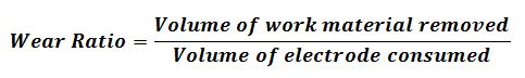
Wear is Best Defined as:
This is Often Simplified to:
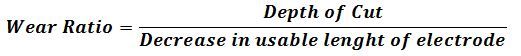
Wear ratio Decrease in the usable length of electrode The wear ratio for carbon electrodes is up to 100: 1. Other wear ratios (for cutting steel) are copper, 2:1; brass, 1:1; and copper tungsten, 8:1. Thus, a piece of copper cutting 25 mm deep into steel will wear 12.5 mm. These ratios are approximate and will vary considerably.
Dielectric Fluids
The essential requirements of dielectric fluid to be used in the EDM process are that they should:
- Remain electrically nonconductive until the required break-down voltage is reached, i.e., they should have high dielectric strength.
- Breakdown electrically in the least possible time once the breakdown voltage has been reached.
- Rapidly quench the spark or deionize the spark gap after the discharges have occurred.
- Provide an effective cooling medium.
- Be capable of carrying away the swarf particles, in suspension, away from the working gap.
- Have a good degree of fluidity.
- Be cheap and easily available.
Light hydrocarbon oils seem to satisfy these requirements best of all. The common dielectrics used are kerosene, paraffin, transformer oil or their mixture and certain aqueous solutions. Water, being an electrical conductor, gives a metal removal rate of only about 40% of that obtained when using paraffin as a dielectric.
The dielectric should be filtered before reuse so that chip contamination of the fluid will not affect machining accuracy. This is usually accomplished by filtration.
Read Also: Types of Welding Defects: [Causes and Remedies] Explained
Metal Removal Rate (MRR)
The metal removal rate is defined as the volume of metal removed per unit of time. The machining rate during roughing of steel with a graphite electrode and 50A generator is about 400 mm/min, and with a 400A generator, it is about 4800 mm/min.
For precision machining with low amperage and high frequency, the material removal rate is as low as 2 mm/min. It is, therefore, evident that the MRR is proportional to the working current value.
The material being cut will affect the MRR. Experiments indicate that the MRR varies inversely to the melting point of the metal.
The approximate value is:
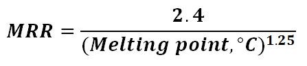
Thus, the electric discharge machining process will cut aluminum much faster than steel.
Read Also: What are the Different Types of Welding Tools and Equipment?
Design Consideration for EDM
- Parts should be designed so that the required electrodes can be shaped properly and economically.
- Deep slots and narrow openings should be avoided.
- The surface finish specified should not be too fine.
- To achieve a high production rate, the bulk of material removal should be done by conventional processes.
Accuracy
A tolerance value of 0.05 mm could be easily achieved by EDM in normal production. However, by close control of the several variables, a tolerance of +0.003 mm could be achieved. A typical taper value is 0.005 to 0.05 mm per 100 mm depth. The tapered effect decreases substantially to zero after about 75 mm penetration.
An overcut of 5 to 100 microns is produced, depending upon finishing or roughing. The best surface finish that can be economically achieved on steel is 0.4 microns. In ‘no wear’ machining, using graphite electrodes, a surface finish within 3.2 microns can be achieved.
Read Also: Types Of CNC Machine [Complete Guide]
Types of Electric Discharge Machining
The EDM procedure is distinctive and common. This does not imply that there is only one method for completing this process, though. EDM can be categorized into three main categories, each employing a different method to achieve the desired outcome.
- Wire EDM (WEDM)
- Sinker EDM (SEDM)
- Hole Drilling EDM (EDM Drilling or EDM Hole Drilling)
#1 Wire EDM (WEDM)
In Wire EDM (WEDM), a thin, electrically conductive wire is used as the electrode. While the workpiece is immersed in dielectric fluid, the wire is continuously fed through it. When an electrical discharge happens between a wire and a workpiece, the material is eroded, and the desired shape is produced.
#2 Sinker EDM (SEDM)
In SEDM, the electrode is shaped to replicate the desired cavity or shape while the workpiece is submerged in dielectric fluid. The electrode is then brought close to the workpiece, and the electrode is subjected to an electrical discharge between the two, which leads to the eroding of the material and the creation of the desired shape.
#3 Hole Drilling EDM (EDM Drilling or EDM Hole Drilling)
As its name implies, this type of EDM is used to drill holes in tough materials that are impossible to drill with conventional techniques. An electrical discharge is used to erode the material and create the hole after shaping the electrode to resemble the desired hole.
Additionally, no deburring is necessary for these holes. This process makes drilling precise holes more efficient and quicker than traditional methods, regardless of the metal’s hardness or type.
Read Also: What are Different Lathe Attachments and Accessories?
Applications of Electric Discharge Machining
- Electrical discharge machining is used for the manufacture of tools having complicated profiles and a number of other components.
- The EDM provides an advantage for making stamping tools, wire drawing and extrusion dies, forging dies, header dies, intricate mold cavities, etc.
- It has been extremely used to manufacture exotic materials used in aerospace industries, refractory metals, hard carbides, and hardenable steels.
- Also, delicate workpieces like copper parts for fitting into the vacuum tubes can be produced by this method. The workpiece, in this case, is fragile to withstand the cutting tool load during conventional machining.
Advantages of Electric Discharge Machining
The extremely high popularity of the EDM process is due to the following advantages:
- The process can be applied to all electrically conducting metals and alloys irrespective of their melting points, hardness, toughness or brittleness.
- Any complicated shape that can be made on the tool can be reproduced on the workpiece.
- Complicated shapes can be done by fabricating the tool with split sectioned shapes.
- Time of machining is less than conventional machining processes.
- EDM can be employed for the extremely hardened workpiece. Hence, the distortion of the workpiece arising out of the heat treatment process can be eliminated.
- No mechanical stress is present in the process. It is due to the fact that the physical contact between the tool and the workpiece is eliminated. Thus, fragile and slender workpieces can be machined without distortion.
- Hard and corrosion-resistant surfaces, essentially needed for die making, can be developed.
Disadvantages of Electric Discharge Machining
The following disadvantages of the process limit its application:
- Profile machining of complex contours is not possible at required tolerances.
- Machining times are too long.
- Machining heats the workpiece considerably and hence causes a change in surface and metallurgical properties.
- Excessive tool wear.
- High specific power consumption.
Closing It Up
That’s it. Thanks for reading if you have any questions about “Electric Discharge Machining,” ask in the comments. If you found this article helpful, please share it with your friends.
Want free PDFs direct to your inbox? Then subscribe to our newsletter.
Download PDF of this article:
Read more:
So nice wow, I like it.
Thanks for reading.
I like this informative article.
Thank you 🙂
Thanks for sharing the informative blog. Keep sharing.
You’re welcome 🙂
Thanks for sharing the tips for cutting tools and I learned information about EDM tools.
My husband and I want to start a business, so I wanted tips on manufacturing partners we should have! I didn’t know EDM machines are good for producing hard carbides and refractory metals. I’ll have to keep that in mind as we hire for our business, so we can have the right machinery making our products, thanks to this post.
You’re welcome and I wish you the best of luck. Congratulations on your startup. May this new business bring you huge success and fulfilment. Good luck and may the good Lord be with you all the way 🙂